Inductive element

a technology of inductive elements and winding windows, which is applied in the direction of transformers/inductances, magnets, magnetic bodies, etc., can solve the problems of less than ideal copper fill factor, affecting and causing coil vibration, etc., to achieve good stability and increase the reliability of the method of manufacture

Active Publication Date: 2011-06-14
DELTA ELECTRONICS (THAILAND) PUBLIC CO LTD
View PDF19 Cites 11 Cited by
  • Summary
  • Abstract
  • Description
  • Claims
  • Application Information

AI Technical Summary

Benefits of technology

[0012]According to the second aspect of the invention the method of manufacture is provided that allows for an efficient and simple manufacture of an inductive element according to the first aspect of the invention. In accordance with the method of manufacture of an inductive element of the second aspect of the invention, at least two core-parts with each having an elongated center piece with an outer winding surface are provided, and the method comprises the steps: a) arranging the core-parts next to each other with their longitudinal axes co-axially aligned; and b) performing a winding process in which an electrical conductor is wound on a winding surface of one or more of the co-axially aligned core-parts.
[0051]Alternatively, the front surfaces of the core-parts can also have further blind-holes which are formed off-center. A corresponding coupling piece then could have corresponding additional projections in order to prevent the core-parts from rotationally slipping with respect to each other due to exceedingly high torque. Insertion of the coupling piece into the blind-holes is then more complicated and assembly of the roll-shaft becomes complicated.

Problems solved by technology

The winding window introduced by the bobbin results in a less than ideal copper fill factor.
The winding windows of bobbins are particularly disadvantageous since the bobbins have to be manufactured with comparatively large tolerances in order to avoid difficulties during assembly of the inductive element, i.e. inserting the legs of the core-parts into openings of the bobbin.
Besides the bad copper fill factors the large tolerances also may be responsible for vibrations of the coils.
Another significant disadvantage of the use of a bobbin is a high thermal resistance between core and winding due to the thermal insulating properties of the bobbin material.
Moreover, the method of manufacture for such a transformer is complex and involves the step of molding a bobbin onto the core and handling the U-shaped core-parts, which are non-symmetric with respect to the winding axis, when performing the winding process.

Method used


Image

  • Inductive element
  • Inductive element
  • Inductive element

Examples


Embodiment Construction

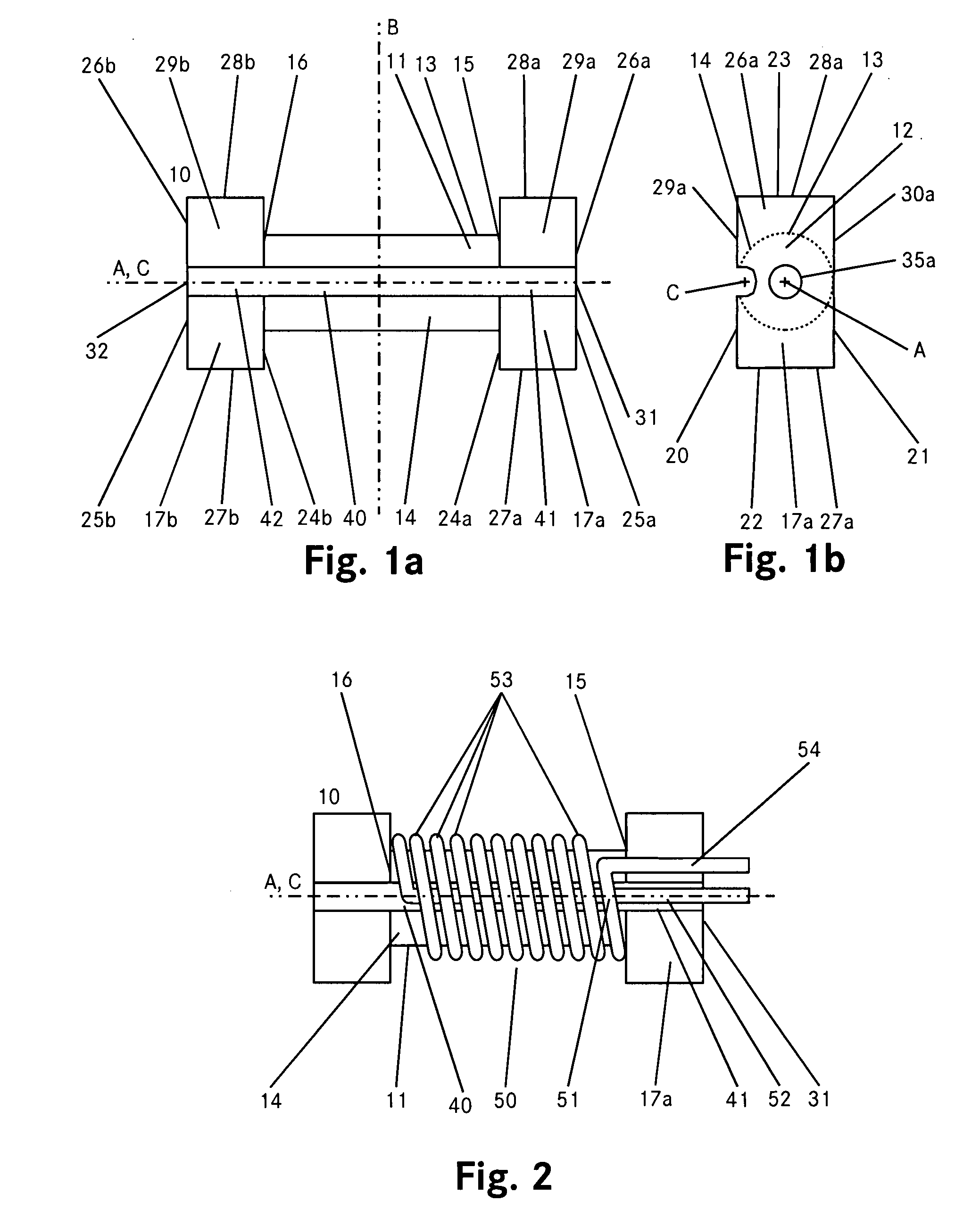
[0061]The embodiment of FIGS. 1a and 1b show a plan view of a core-part 10 of an inductive element according to the invention from two different directions. FIG. 1a shows the view perpendicular to a longitudinal axis A of the core-part 10 and FIG. 1b shows a view along the axis A.

[0062]The core-part 10 comprises an elongated cylindrical center piece 11 with its longitudinal axis co-axially aligned with the axis A. The center piece 11 has a circular cross section 12 and, with respect to the axis A, an outer (superficies) surface 13 forming a winding surface 14. The center piece 11 has at each of its longitudinal ends 15 and 16 a contact element 17a and 17b, respectively. The core-part 10 is symmetrically formed with respect to a plane B which is perpendicular to the longitudinal axis A and goes through the longitudinal middle of the center piece 11. The contact elements 17a and 17b are also symmetrically arranged with respect to the plane B. In other embodiments not shown here, the c...


PUM

PropertyMeasurementUnit
angleaaaaaaaaaa
angleaaaaaaaaaa
magnetically permeableaaaaaaaaaa

Abstract

An inductive element comprises at least two core-parts including a magnetically permeable material and at least one winding of an electrical conductor which can be a foil winding, a stranded wire (litz) winding or a conventional wire winding. Each core-part has an elongated center piece with an outer winding surface. At each of its longitudinal ends, the center piece has a contact element with a lateral contact surface. The winding is wound directly on the core-parts without a bobbin or the-like. The core-parts of the inductive element are arranged with their longitudinal axes essentially in parallel in a manner that the lateral contact surfaces of each contact element abut on a lateral contact surface of another core-part. Such an inductive element can be manufactured by co-axially arranging the core-parts and using them as a roll-shaft. After the windings have been applied to the core-parts, they can be rearranged, i.e. “flipped over,” in a stack-like arrangement in order to form an inductive element.

Description

CROSS REFERENCE TO RELATED APPLICATIONS[0001]This application claims priority from the European patent application No. 06 405 376.2 filed Sep. 1, 2006 in the name of DET International Holding Limited entitled “Inductive Element,” incorporated herein by reference.FIELD OF THE INVENTION[0002]The invention relates to an inductive element and a method of making an inductive element, wherein the inductive element comprises at least two core-parts, where the core-parts include a magnetically permeable material. More particularly the invention relates to an inductive element and method utilizing modular core parts and absent a bobbin.BACKGROUND[0003]Common designs for high power inductors and chokes used in switching mode applications have constructions incorporating coils with bobbins for carrying the windings and isolating them from a permeable core. The core, which is typically manufactured with assemblies comprising U-shaped core-parts, thereby acts as a magnetic flux path. The two U-s...

Claims


Application Information

Patent Timeline
Patent Type & Authority Patents(United States)
IPC IPC(8): H01F27/28H01F27/24H01F7/06
CPCH01F17/045H01F3/10Y10T29/49071Y10T29/4902Y10T29/49073H01F27/292
Inventor PILNIAK, JURGENWALLMEIER, PETER
Owner DELTA ELECTRONICS (THAILAND) PUBLIC CO LTD
Why Eureka
Try Eureka