Electronic equipment and method in electronic equipment for forming image information and a program product or implementation of the method

a technology of electronic equipment and image information, applied in the field of electronic equipment, can solve the problems of unsuitable imaging method, unsuitable image, undesirable distortion, etc., and achieve the effect of reducing the cost of image processing, and reducing the quality of image processing

Active Publication Date: 2011-06-14
NOKIA TECHNOLOGLES OY
View PDF18 Cites 35 Cited by
  • Summary
  • Abstract
  • Description
  • Claims
  • Application Information

AI Technical Summary

Benefits of technology

Integration of the method according to the invention both in present-day electronic equipment and in those being planned can be performed quite simply. According to one embodiment, the equipment can also be provided additional with second camera unit only, with the control functions of the camera units and also with some program modules in order to allow different imaging modes.

Problems solved by technology

Instead, if the imaged object is in motion, such an imaging method is rather unsuitable.
If the location of the camera is not sufficiently exact, so-called artefacts, i.e. undesirable distortions, will then appear in the image.
However, the lens arrangement constitutes a very complicated and even cost-intensive whole, where the size factors of portable equipment also cause limitations of their own.
Known portable electronic equipment also provided with an integrated camera functionality have so far entirely lacked the panorama imaging functionality.
Furthermore, known kinds camera means and especially the image sensors they apply are only capable of a certain and quite limited image resolution.
This poses a problem to do with the resolution of the image, and the problem cannot be solved at least with image sensors of the known kinds.
If improved resolution is desired, this requires sensors of a better quality, but applying these will raise the consumer price of the equipment.
And furthermore, if e.g. enlargements are to be made of the image, the limited resolution will cause problems, for example, in the form of granularity.
The camera arrangement described, in which the mutual position of the cameras relative to each other, is fixed, is not, however, the best possible for producing 3D image information, not it is suitable for implementing more diverse imaging modes.

Method used


Image

  • Electronic equipment and method in electronic equipment for forming image information and a program product or implementation of the method
  • Electronic equipment and method in electronic equipment for forming image information and a program product or implementation of the method
  • Electronic equipment and method in electronic equipment for forming image information and a program product or implementation of the method

Examples


Embodiment Construction

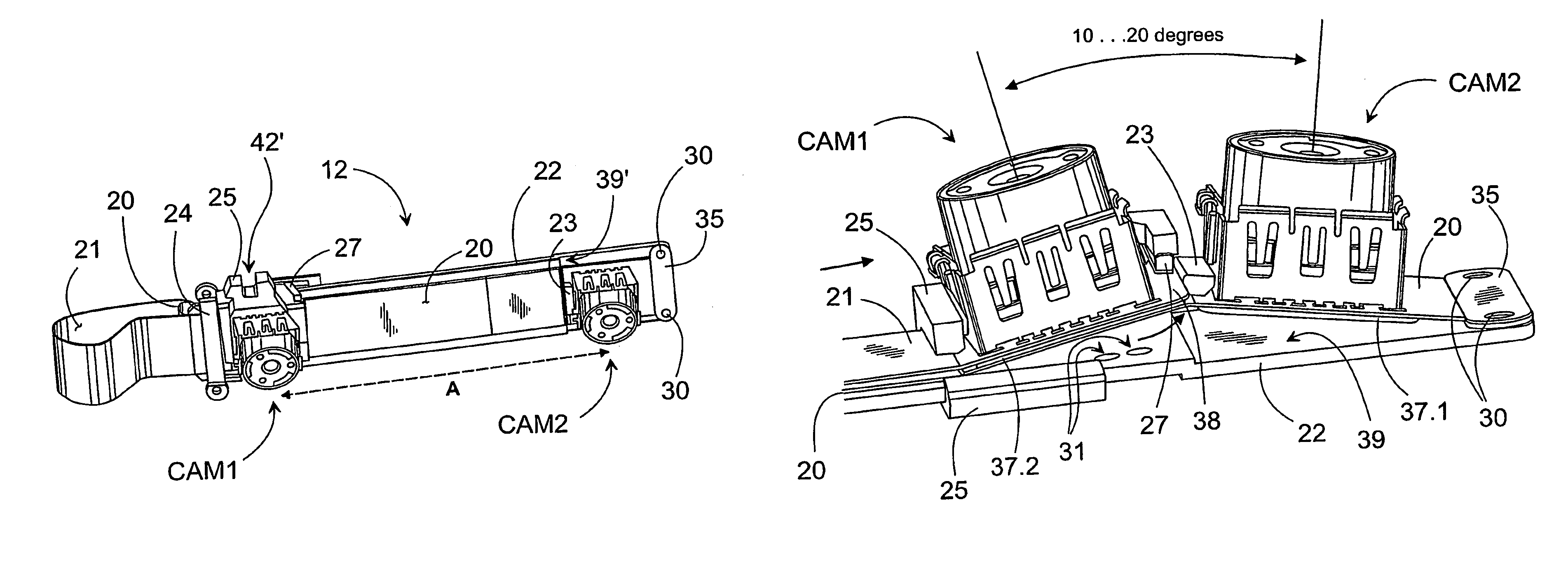
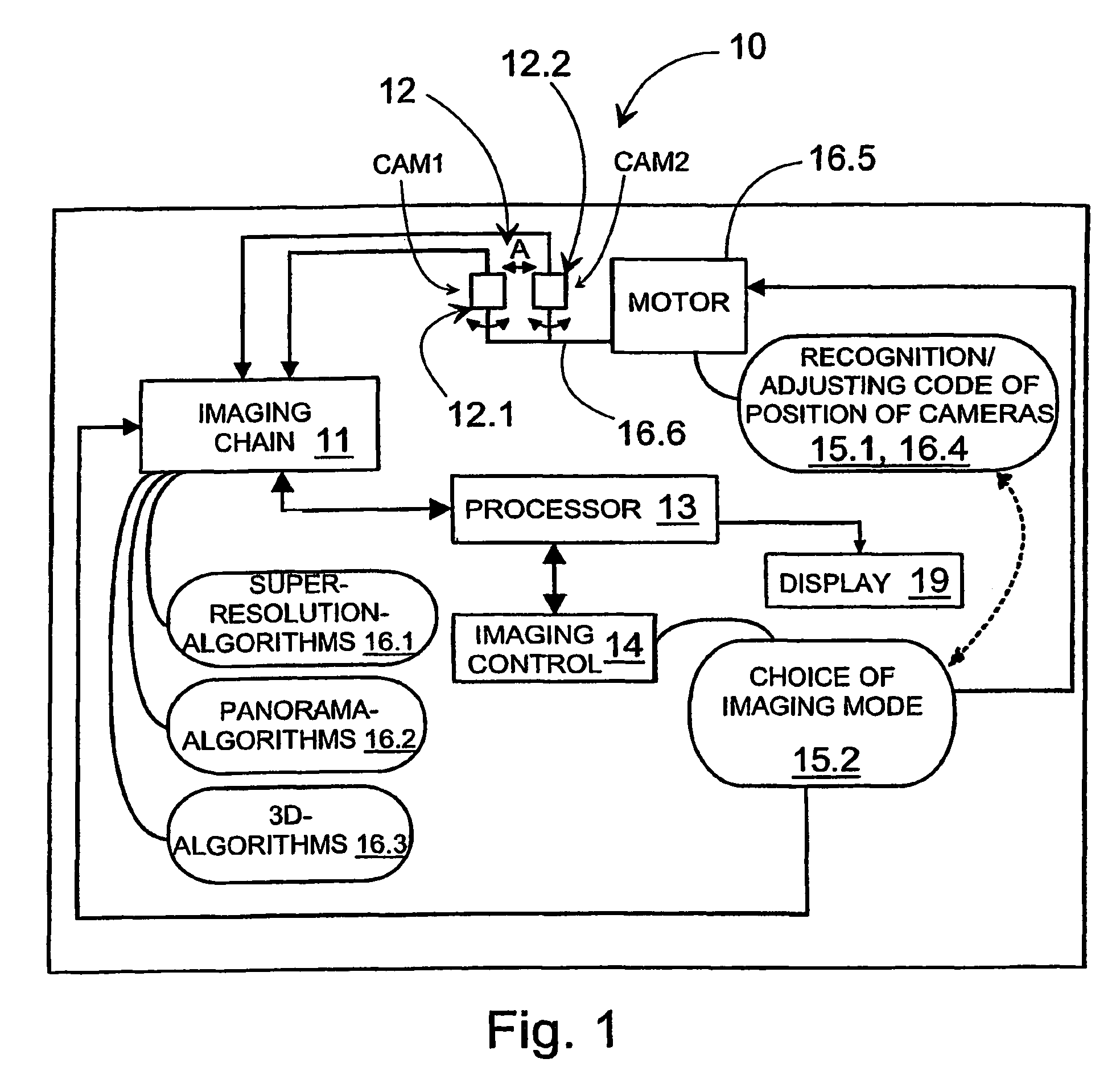
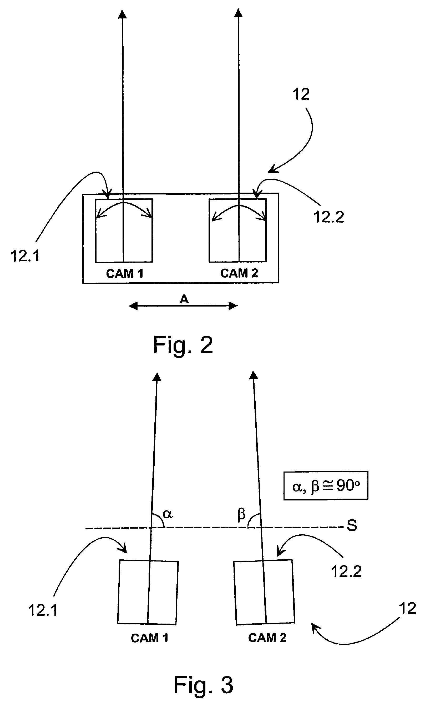
Nowadays, many electronic equipment 10 often includes camera means. Besides digital cameras, examples of such equipment are mobile stations, PDA (Personal Digital Assistant) equipment and other such “intelligent devices of communication”, of which equipment of the Palm type can be mentioned as an example. The concept of “electronic equipment” can in fact be understood even quite largely in this context. For example, it may be such a piece of equipment, which is provided with or can be provided with a digital imaging ability. In the following, the invention will be described by way of example in connection with a mobile station 10.

FIG. 1 shows a rough schematic example of functions in equipment 10 as regards their parts to do with the invention, which also constitute the system at the same time. Equipment 10 may include the functional parts shown in FIG. 1, which are of a known kind as such and of which the camera means 12 may be mentioned as parts essential for the implementation of...


PUM


Abstract

The invention relates to electronic equipment. The equipment includes camera means for forming data from an object located in the imaging direction, in which case the said camera means include at least two camera units (CAM1, CAM2) and data-processing means, which are arranged to process the data formed using the camera means, in a manner corresponding to the currently selected imaging mode, to form image information. In the equipment, the mutual position of the camera units (CAM1, CAM2) relative to each other is arranged to be altered to correspond to the current imaging mode.

Description

TECHNICAL FIELDThe invention concerns electronic equipment, which includescamera means for forming data on an object located in the imaging direction, in which case the said camera means include at least two camera units anddata processing means, which are arranged to process the data formed by the camera means, according to the currently chosen imaging mode of the equipment, in order to form image information.In addition, the invention also concerns a system, method, program product, and camera module.BACKGROUNDElectronic equipment, for example, portable equipment, is nowadays equipped with one camera unit. Such an arrangement is in fact quite adequate for performing ordinary still and video imaging with moderate resolution. However, along with the development, future equipment and their circle of users will demand development of new manners of imaging.One example of these new imaging manners is 3D imaging. Equipment to be launched on the markets in the future will have three-dimen...

Claims


Application Information

Patent Timeline
Patent Type & Authority Patents(United States)
IPC IPC(8): H04N5/247H04N15/00H04N5/225G06K9/00G03B35/00H04N13/00
CPCH04N13/0239H04N13/239H04N13/00
Inventor VIINIKANOJA, JARKKOEROMAKI, MARKO
Owner NOKIA TECHNOLOGLES OY
Why Eureka
Try Eureka