Polarization beam splitter and polarization conversion element

a polarization beam and splitter technology, applied in the field of polarization beam splitter and polarization conversion element, can solve the problems of difficult to enhance the efficiency of manufacturing polarization beam splitter, insufficient polarization-splitting performance, and inability to exhibit polarization-splitting function for reddish light, etc., to achieve excellent polarization-splitting function, low cost, and favorable polarization-splitting function

Inactive Publication Date: 2011-06-14
RICOH KK
View PDF11 Cites 4 Cited by
  • Summary
  • Abstract
  • Description
  • Claims
  • Application Information

AI Technical Summary

Benefits of technology

[0014]The present invention provides a polarization beam splitter and a polarization conversion element in which one or more of the above-described disadvantages are eliminated.
[0015]A preferred embodiment of the present invention provides a polarization beam splitter and a polarization conversion element including the same, in which a polarization split film can be formed of a relatively small number of laminated layers in each dielectric multilayer film and a favorable polarization-splitting function can be realized across a wide visible wavelength region, specifically in a range of 400 nm through 750 nm.
[0017]According to one embodiment of the present invention, a polarization beam splitter and a polarization conversion element including the same are provided, in which a polarization split film can be formed of a relatively small number of laminated layers in each dielectric multilayer film and a favorable polarization-splitting function can be realized in a wide visible wavelength region ranging from 400 nm through 750 nm with respect to light with an incidence angle that falls in a range of 54 degrees through 66 degrees.
[0018]Each transparent substrate can be made of low-cost and readily available optical glass having a refractive index that falls in a range of 1.46 through 1.58, such as BK7. The high refractive index films in each dielectric multilayer film can be made of a low-cost material that can be realized with a refractive index of around 2.3, such as Nb2O5. Accordingly, a low-cost polarization beam splitter can be provided.
[0019]The polarization beam splitter according to an embodiment of the present invention has an excellent polarization-splitting function, and therefore the polarization conversion elements formed with such polarization beam splitters can realize favorable polarization conversion properties.

Problems solved by technology

However, the transmittance of an S polarization component was around 15% with respect to light in a wavelength range of 400 nm through 700 nm, which is insufficient in terms of polarization-splitting performance.
Therefore, the polarization-splitting function cannot be exhibited for reddish light.
It will be time consuming to form the polarization split film if the number of laminated layers in each dielectric multilayer film is large, which makes it difficult to enhance the efficiency in manufacturing polarization beam splitters.
Such high refractive index glass and high refractive index substances are expensive, which will make it difficult to mass-produce polarization beam splitters at low cost and with high efficiency.

Method used


Image

  • Polarization beam splitter and polarization conversion element
  • Polarization beam splitter and polarization conversion element
  • Polarization beam splitter and polarization conversion element

Examples


example 1

Practical Example 1

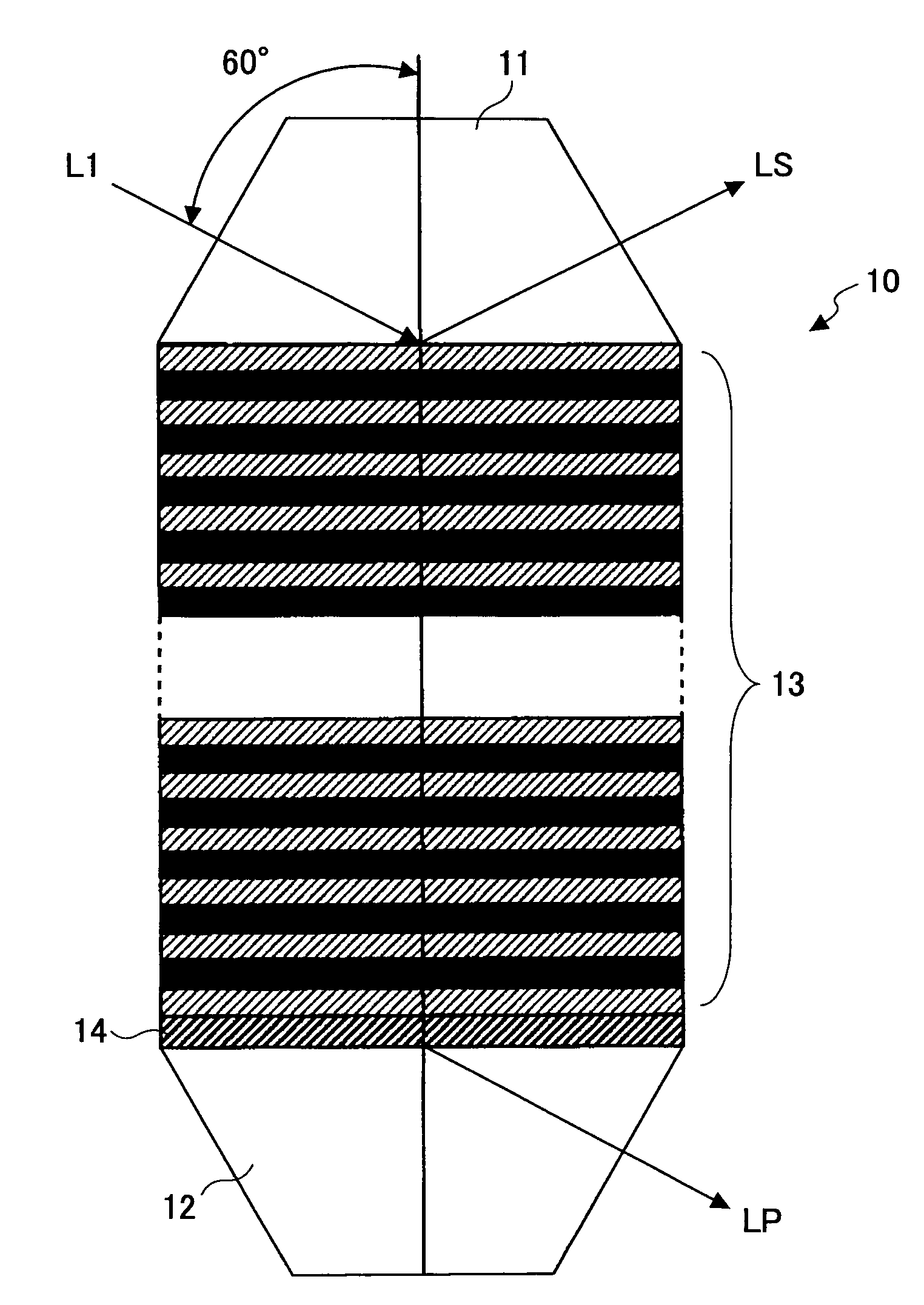
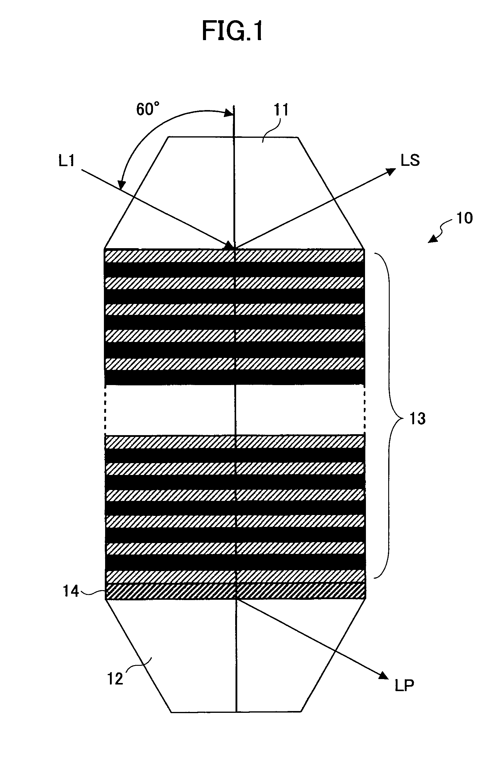
[0051]As shown in FIG. 1, the polarization beam splitter according to practical example 1 is designed to have an incidence angle of 60 degrees. Table 1 shows the configuration of the polarization beam splitter according to practical example 1.

[0052]

TABLE 1CENTERFILMPHYSICALWAVE-THICK-FILMLENGTHREFRACTIVENESSTHICKNESSLAYERSUBSTANCEλ 0INDEX nndd(nm)nd = λ 0 / 4SUBSTRATEBSC7————DIFFERENT1Nb2O5 / SiO2840.01.5720.25λ133.60MID-REFRACTIVEFIRST2Nb2O5610.02.2130.25λ68.90INDEX FILMMULTILAYER3Nb2O5 / SiO2610.01.6130.25λ94.60FILM4Nb2O5610.02.2130.25λ68.905Nb2O5 / SiO2610.01.6130.25λ94.606Nb2O5610.02.2130.25λ68.907Nb2O5 / SiO2610.01.6130.25λ94.608Nb2O5610.02.2130.25λ68.909Nb2O5 / SiO2610.01.6130.25λ94.6010Nb2O5610.02.2130.25λ68.9011Nb2O5 / SiO2610.01.6130.25λ94.6012Nb2O5610.02.2130.25λ68.9013Nb2O5 / SiO2610.01.6130.25λ94.6014Nb2O5610.02.2130.25λ68.9015Nb2O5 / SiO2610.01.6130.25λ94.60SECOND16Nb2O5830.02.1700.25λ95.60MULTILAYER17Nb2O5 / SiO2830.01.6230.25λ127.90FILM18Nb2O5830.02.1700.25λ95.6019Nb2O...


PUM


Abstract

A disclosed polarization beam splitter is effective when light to undergo polarization-splitting has an incidence angle that falls in a range of 54 degrees through 66 degrees. The polarization beam splitter includes, between two transparent substrates, an adhesive layer configured to adhere to a first transparent substrate of the two transparent substrates, two or more types of dielectric multilayer films having different design basis wavelengths, and a single-layer dielectric film. The dielectric multilayer films and the single-layer dielectric film form a polarization split film, which performs a polarization split function with respect to light that is substantially in the visible wavelength region.

Description

BACKGROUND OF THE INVENTION[0001]1. Field of the Invention[0002]The present invention relates to a polarization beam splitter and a polarization conversion element.[0003]2. Description of the Related Art[0004]A polarization beam splitter typically includes a polarization split film sandwiched between a pair of transparent substrates. The polarization beam splitter is an optical element for splitting incident light into transmitted light and reflected light having polarization planes that are orthogonal to each other. The polarization beam splitter is used in various types of optical devices.[0005]When the polarization beam splitter is used in an optical device using monochromatic light such as an optical pickup, favorable polarization-splitting properties can be realized relatively easily. However, when the polarization beam splitter is used as a polarization conversion element in a liquid crystal projector, it is required to have favorable polarization-splitting properties across t...

Claims


Application Information

Patent Timeline
Patent Type & Authority Patents(United States)
IPC IPC(8): G02B5/30
CPCG02B5/3041
Inventor MAEDA, IKUOSHIBATA, KAZUSI
Owner RICOH KK
Why Eureka
Try Eureka