Radial compression mechanism with optimum die-to-die gap

a compression mechanism and radial compression technology, applied in the field of mechanisms, can solve the problems of large gaps between the wedges, metal struts of the stent can move into the gap and be damaged, and the wedge-shaped working end typically does not provide a sufficiently accurate positional relationship

Active Publication Date: 2011-06-21
GOFF ED
View PDF9 Cites 20 Cited by
  • Summary
  • Abstract
  • Description
  • Claims
  • Application Information

AI Technical Summary

Problems solved by technology

A shortcoming of this type of mechanism is that there exists a gap between adjacent wedges, the size of which varies with the diameter of the cavity in an undesirable way.
The strict design tradeoffs for this type of mechanism results in a mechanism that must be large to provide a small maximum gap for a given diameter range, or a mechanism that must have a large gap to provide the same diameter range in a small size.
Large gaps between the wedges are a disadvantage because they allow space for parts of the compressed device to go into.
For example, the metal struts of a stent can move into the gap and be damaged.
A shortcoming of this mechanism is that it typically does not provide a sufficiently accurate positional relationship of the wedge-shaped working ends of the dies.
Medical device manufacturing and testing often requires an accurately round cavity at diameters as small as 0.3 mm. which is typically not achieved by this type of mechanism.

Method used


Image

  • Radial compression mechanism with optimum die-to-die gap
  • Radial compression mechanism with optimum die-to-die gap
  • Radial compression mechanism with optimum die-to-die gap

Examples


Embodiment Construction

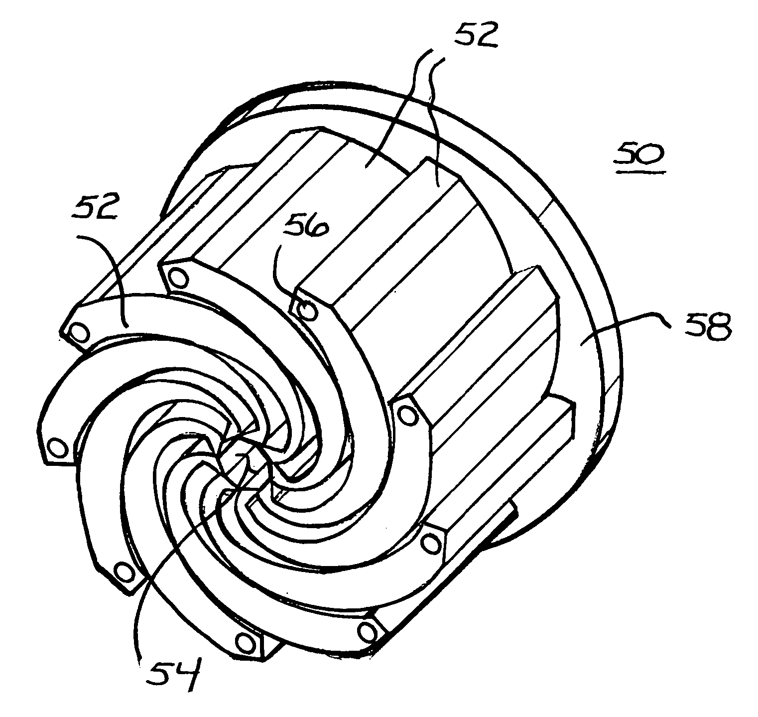
[0027]Turning now to the drawings, attention is first directed to FIGS. 11-17, which illustrate various perspective views of a radial compression mechanism 10 in accordance with the present invention. Mechanism 10 includes a housing 12 with a pair of spaced apart hinge plates 14 and 16. Hinge plate 16 has a product receiving opening 18 formed approximately centrally therethrough, an enlarged view of which can be seen in FIG. 12 Hinge plate 16 has a crank mechanism 20 mounted on the outer surface thereof that is coupled to rotatably drive a plurality of hinged or pivotally mounted die, designated 22. Each die 22 has a working surface 24 at an inner end and a pair of spaced apart pivot points 26 (seen for example in FIG. 15) at the other end. Each die 22 of the plurality of dies is mounted at one pivot point 26 by a pivot pin 28 engaged in hinge plate 14 and at the other pivot pin 26 by a pivot pin 28 engaged in hinge plate 16.

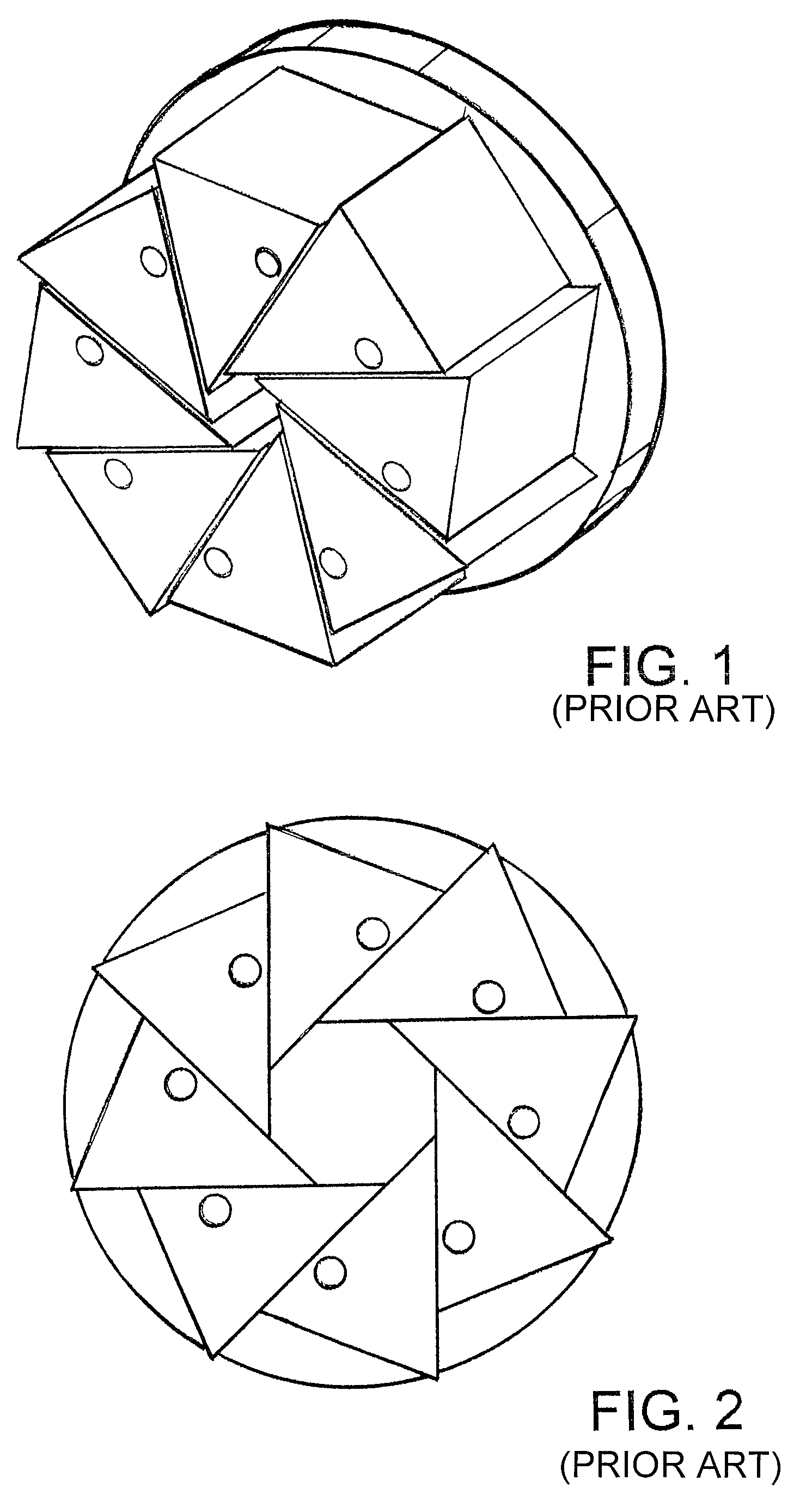
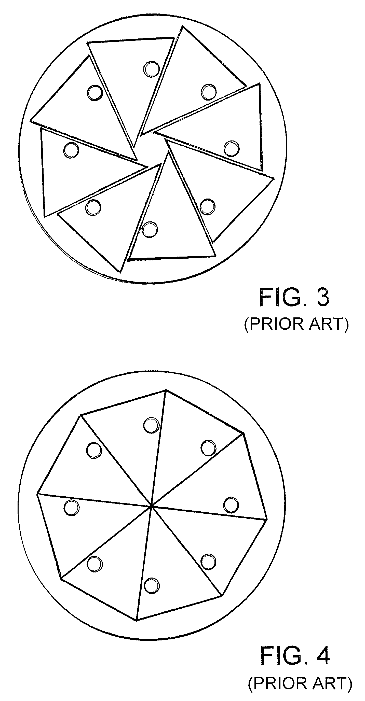
[0028]Referring specifically to FIG. 12, each die 22 is po...


PUM

PropertyMeasurementUnit
diameteraaaaaaaaaa
widthaaaaaaaaaa
diametersaaaaaaaaaa

Abstract

Radial compression mechanism includes a plurality of dies each having an elongated arcuate body with an outer end pivotally attached to a hinge plate and an inner working tip. The dies are mounted on the hinge plate in an inwardly spiraling orientation with the outer ends positioned in a circle and the working tips cooperating to define a central product-receiving cylindrically-shaped cavity. The product-receiving cavity is transitional between an open and a closed orientation. The working tip of each die has a sliding surface and a working surface with the sliding surface positioned in parallel juxtaposition to the working surface of an adjacent die and a constant width gap therebetween. Driving mechanism is coupled to rotatably drive all of the dies in unison to transition between open and closed orientations. The width of the gap remains constant during transition and between the open and closed orientations.

Description

FIELD OF THE INVENTION[0001]This invention generally relates to radial compression mechanisms and more specifically to mechanisms for compressing devices such as stents, catheters, balloons, and the like.BACKGROUND OF THE INVENTION[0002]In the manufacture and testing of medical devices, mechanisms are used to radially compress cylindrical devices such as stents, balloons, and catheters. For example, installation of a stent onto a catheter balloon is typically done by compressing the stent radially inward onto the balloon with enough pressure to permanently deform the stent to a smaller diameter and to slightly embed the metal stent into the plastic balloon. In another example, a polymer catheter balloon is compressed radially after pleating to wrap it tightly around the catheter shaft. In another example, a self-expanding stent is radially compressed to insert it into a sheath or delivery system. In an example of medical device testing, a stent is radially compressed while the requi...

Claims


Application Information

Patent Timeline
Patent Type & Authority Patents(United States)
IPC IPC(8): B21D41/04B23Q1/00
CPCA61F2/95B21J9/06A61F2002/9522Y10T29/53987Y10T29/53996A61F2/9522
Inventor GOFF, ED
Owner GOFF ED
Why Eureka
Try Eureka