Inspection apparatus and inspection method using electromagnetic wave

a technology of electromagnetic wave and inspection apparatus, applied in the direction of photometry using electric radiation detectors, specific gravity measurement, instruments, etc., can solve the problems of large system size and high cost, insufficient inspection speed, and inability to use the conventional thz-tds apparatus for a total inspection in the factory

Inactive Publication Date: 2011-06-21
CANON KK
View PDF33 Cites 5 Cited by
  • Summary
  • Abstract
  • Description
  • Claims
  • Application Information

AI Technical Summary

Benefits of technology

[0015]According to the inspection apparatus and method of the present invention, different sites of an inspection object are irradiated with an electromagnetic wave, and the electromagnetic wave which is reflected or transmitted with interacting with these are acquired by a plurality of detection units as signals in different detection time or different frequencies. In consequence, it is possible to obtain the electromagnetic wave response information of the inspection object which is constructed of a plurality of specimens of the same kind or a homogeneous specimen at high speed as average information.

Problems solved by technology

Therefore, a conventional THz-TDS apparatus cannot be applied to a total inspection in a factory production line.
In that case, in order to compensate low conversion efficiency, a titanium sapphire laser is required as a large output excitation light source, and hence, the system becomes large-sized and expensive.
In addition, although this system is to obtain spectral information in each point, inspection speed is not enough to use this system for a total inspection in a factory.

Method used


Image

  • Inspection apparatus and inspection method using electromagnetic wave
  • Inspection apparatus and inspection method using electromagnetic wave
  • Inspection apparatus and inspection method using electromagnetic wave

Examples


example 1

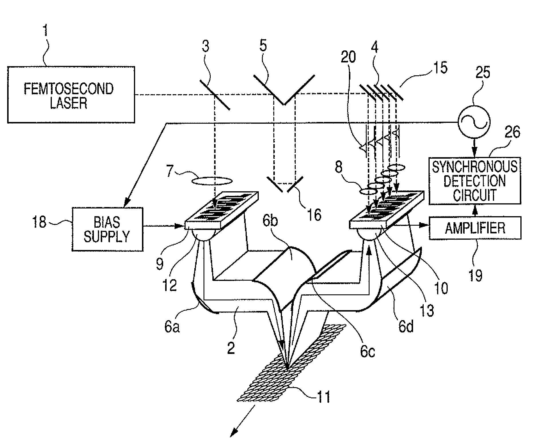
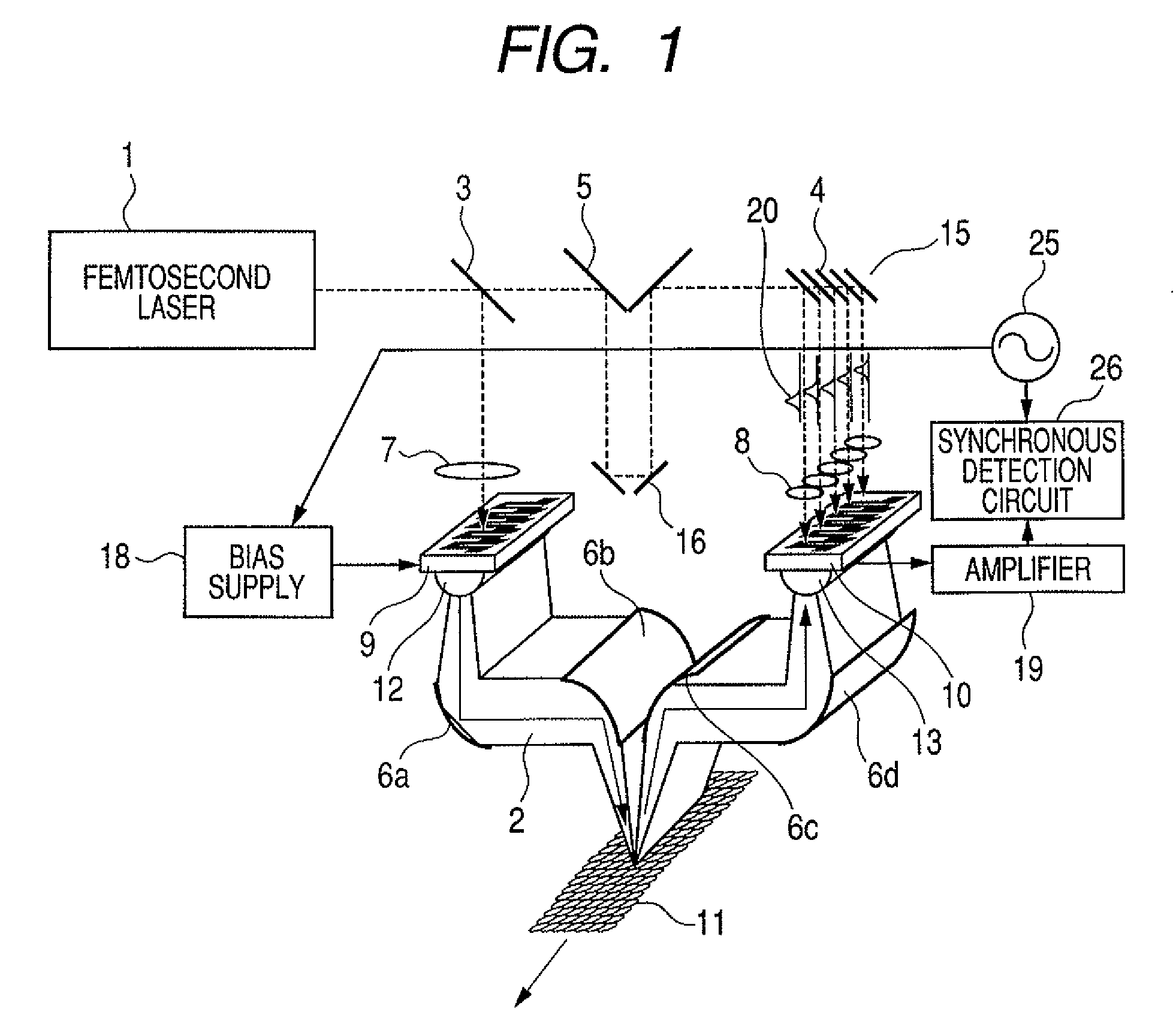
[0039]A first example according to the present invention uses a terahertz time domain spectrum (THz-TDS) apparatus, as illustrated in FIG. 1 mentioned above, as a base. In this example, devices where electrodes are patterned on low-temperature growth gallium arsenide (LT-GaAs) are used as the photoconductive devices 9 and 10. Using the femtosecond laser 1 with a pulse width of 120 fsec and a wavelength of 780 nm, this example irradiates a 30-mW laser beam simultaneously on all the elements of the array of the photoconductive device 9 in a generation side to generate a broad terahertz beam. In this example, the specimen 11 is a drug manufactured at high speed, and moves in an arrow direction.

[0040]When being condensed into a line by the parabolic reflector 6b, as shown in FIG. 1, the broad terahertz beam 2 is irradiated on the plurality of tablets 11 simultaneously, and the tablet samples move sequentially also during measurement. Then, the terahertz wave reflected by these tablets i...

example 2

[0052]A second example according to the present invention controls a whole pharmaceutical preparation process using the inspection apparatus of the first example. According to the inspection apparatus and method of pharmaceutical preparations according to the present invention, it is possible to perform an inspection of almost all specimens nondestructively and in real time, and to inspect information, including average components of a plurality of specimens of the same kind or a homogeneous specimen, and the like. Therefore, it is possible to respond to a change like a drift under manufacturing, and the like with high accuracy.

[0053]FIG. 6 is a block diagram of a system which manages a manufacturing process using an inspection apparatus. This system inspects many tablets or the like, which are manufactured by a pharmaceutical preparation apparatus and move from there, by the inspection apparatus of the present invention, and discards a part of tablets by a screening apparatus when ...

example 3

[0055]Depending on an application to which it is used, a solid state laser type described in the embodiments and examples mentioned above may affect apparatus performance by a degree of stability and long term deterioration of an electromagnetic wave oscillation light output. Then, a third example according to the present invention introduces a beam for terahertz wave excitation with a fiber. Whole structure is almost the same as that of the first example as illustrated in FIG. 7, but a femtosecond laser 50 is a fiber laser types and an optical output is supplied by an optical fiber 51.

[0056]The optical output is divided into two by an optical branching coupler 52. One of them is introduced by the optical fiber 54 into a terahertz conversion part 55 that the same photoconductive device and optical system as those in FIG. 1 are modularized into one, and generates a terahertz wave 57.

[0057]Although doted lines illustrate a propagation path of the terahertz wave 57 in FIG. 7, in fact, ...


PUM

PropertyMeasurementUnit
poweraaaaaaaaaa
delay timeaaaaaaaaaa
wavelengthaaaaaaaaaa

Abstract

The present invention is to provide inspection apparatus and method of being able to acquire electromagnetic wave response information of an inspection object at high speed as average information using an electromagnetic wave. An inspection apparatus using an electromagnetic wave 2 includes an electromagnetic wave generation and irradiation unit 9 which generates an electromagnetic wave and irradiates the electromagnetic wave on an inspection object 11, and an electromagnetic wave detection unit 10 having a plurality of detection units. The plurality of detection units is arranged so as to detect the electromagnetic wave which is irradiated by the electromagnetic wave generation and irradiation unit and is transmitted or reflected with interacting with different sites of the inspection object 11, and is constructed so as to detect the electromagnetic wave from the different sites in different detection time or detection frequencies respectively. The inspection apparatus acquires electromagnetic wave response information on the inspection object 11 based on detection signals from the plurality of detection units.

Description

BACKGROUND OF THE INVENTION[0001]1. Field of the Invention[0002]The present invention relates to an inspection apparatus, an inspection method, and the like which acquire information on a character and the like of a specimen using an electromagnetic wave. In particular, the present invention relates to an inspection apparatus, an inspection method, and the like which acquire information on an object character and the like using an electromagnetic wave in a frequency domain from a millimeter wave band to a terahertz band (30 GHz to 30 THz).[0003]2. Related Background Art[0004]Nondestructive sensing techniques using an electromagnetic wave in a frequency domain from a millimeter wave band to a terahertz band (30 GHz to 30 THz) (hereafter, it is simply called a terahertz (THz) wave) have been developed. Imaging using an electromagnetic wave in a frequency domain of a terahertz band has been developed, and has received attention as a safe see-through inspection apparatus which replaces ...

Claims


Application Information

Patent Timeline
Patent Type & Authority Patents(United States)
IPC IPC(8): G01N21/31G01J1/42G01N21/35G01N21/3504G01N21/3586
CPCG01N21/3581G01N21/8806G01N21/94G01N21/9508G01N2021/845
Inventor OUCHI, TOSHIHIKO
Owner CANON KK
Why Eureka
Try Eureka