Local perfusion device

a perfusion device and local technology, applied in the field of medical devices, can solve the problems that the distal end of the device cannot be advanced through the body, and achieve the effects of low profile, convenient use, and maintaining blood flow

Inactive Publication Date: 2011-06-21
BOSTON SCI SCIMED INC
View PDF71 Cites 0 Cited by
  • Summary
  • Abstract
  • Description
  • Claims
  • Application Information

AI Technical Summary

Benefits of technology

Overcoming the problems associated with cooling a local area leads to the requirements of a device that is preferably low-cost, easy to use, simple, capable of maintaining blood flow during the reduced temperature timeframe, capable of utilizing multiple types of cold media, low profile, and easy to manufacture.

Problems solved by technology

Likewise, the distal end of the device cannot be advanced through the body when the structure is in a deployed state.

Method used


Image

  • Local perfusion device
  • Local perfusion device
  • Local perfusion device

Examples


Embodiment Construction

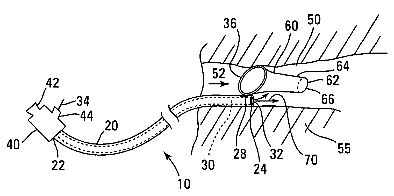
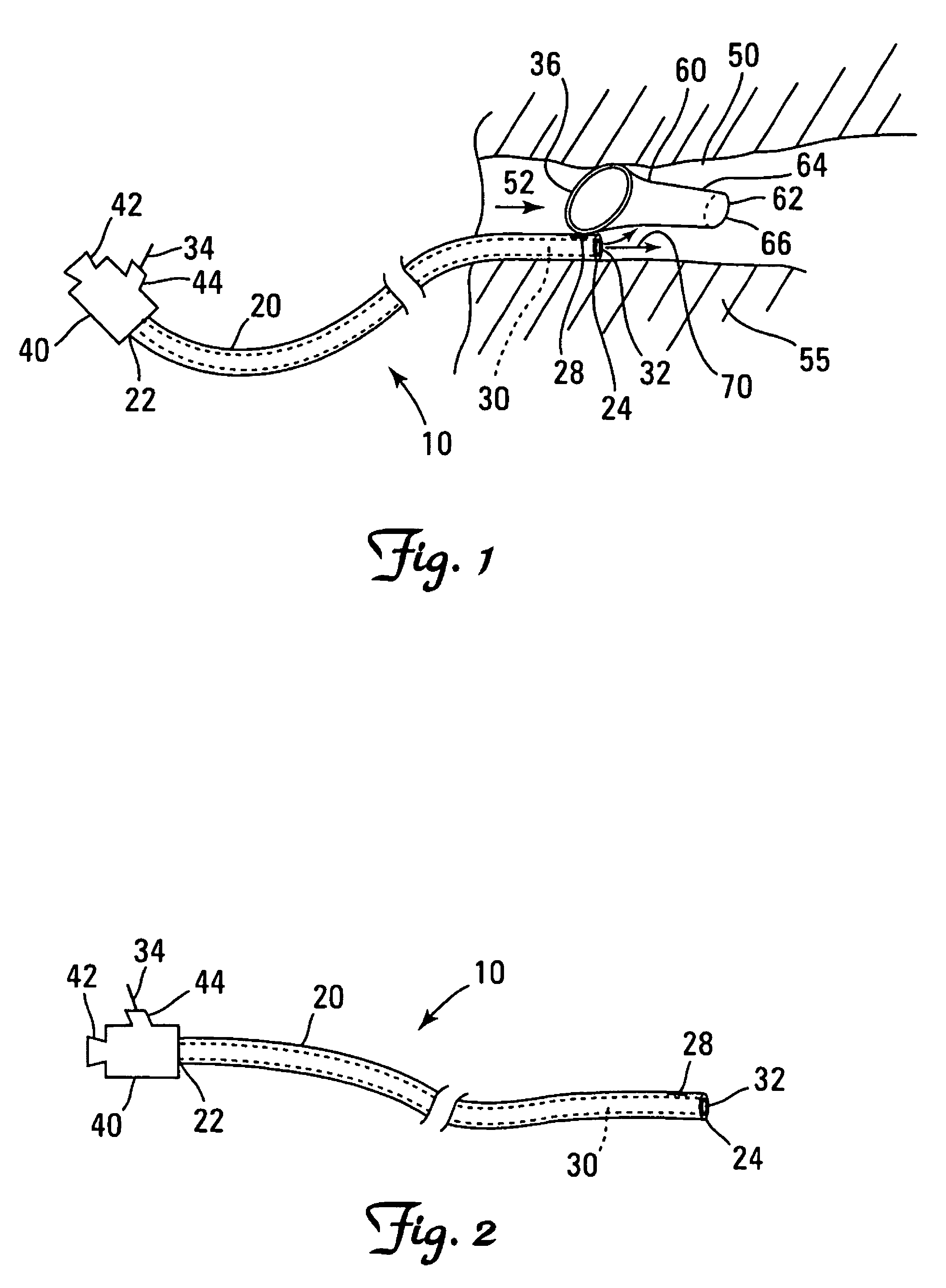
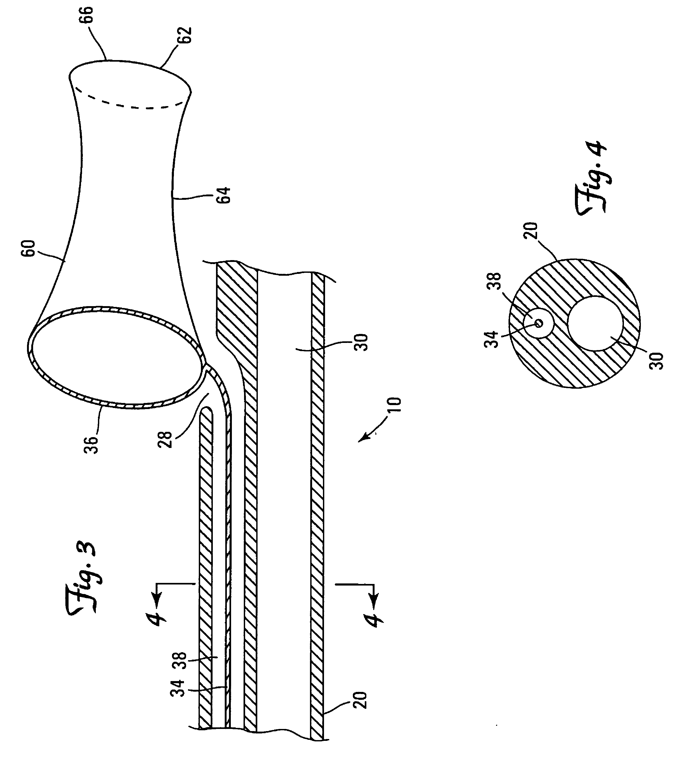
FIGS. 1, 2, 3, and 4 show one embodiment of a local cooling device 10. The local cooling device 10 may be inserted into and advanced to reach a target location 50 within the body, such as in a vessel 55.

The local cooling device 10 includes an elongate shaft 20 and has a perfusion lumen 30 extending longitudinally therethrough. The perfusion lumen 30 extends from a proximal end 22 to a distal end 24 of the cooling device 10. An adapter 40 is attached to the proximal end 22 of the cooling device 10. Fluid 70 may be introduced into the perfusion lumen 30, pass through the perfusion lumen 30 and exit near the distal end 24 of the cooling device 10. The fluid 70 treats target location 50. A wire loop 36 and blood channeler 60 may be deployed from the cooling device 10 (as shown in FIG. 1) to divert blood flowing through the body vessel away from the target location 50.

This may be useful in various treatments. For example, a cooled fluid may be passed through the perfusion lumen 30 while ...


PUM


Abstract

A device for providing a fluid to a target tissue region of a body vessel is described. The device includes an elongate member having a lumen to receive a fluid, and a structure deployable from a distal portion of the elongate member to channel blood flowing in the vessel. Also described are a method of, and a system for, providing a fluid to a target tissue region inside a body.

Description

TECHNICAL FIELDThis invention relates to medical devices, and more particularly to local cooling devices.BACKGROUNDMyocardial ischemia, and in severe cases acute myocardial infarction (AMI), can occur when there is inadequate blood circulation to the myocardium due to coronary artery disease. Evidence suggests that early reperfusion of blood into the heart, after removing a blockage to blood flow, reduces damage to the myocardium. However, the reestablishment of blood flow into the heart may cause a reperfusion injury to occur. Reperfusion injury is believed to be due to the build up of waste products on the myocardium during the time blood flow was inadequate and the reaction of these waste products with oxygen in the blood when normal blood flow is reestablished. It is possible to reduce reperfusion injury to the myocardium by cooling the myocardial tissue prior to reperfusion. Mild cooling of the myocardial tissue to a temperature between 28 and 36 degrees Celsius provides a prot...

Claims


Application Information

Patent Timeline
Patent Type & Authority Patents(United States)
IPC IPC(8): A61M29/00
CPCA61F7/12A61F2007/126A61F2007/0063
Inventor HOLMAN, THOMAS J.WEBER, JANEIDENSCHINK, TRACEE
Owner BOSTON SCI SCIMED INC
Why Eureka
Try Eureka