Network management system and graphical user interface

a network management system and user interface technology, applied in the field of network management system, can solve the problems of difficult configuration, considerable time-consuming, and difficult configuration

Inactive Publication Date: 2011-06-21
QWEST
View PDF44 Cites 187 Cited by
  • Summary
  • Abstract
  • Description
  • Claims
  • Application Information

AI Technical Summary

Benefits of technology

[0006]It is, therefore, an object of the present invention to provide a network management system for configuring a network connection between first and second service access points that utilizes an information manager and a configuration manager to utilize a generic set of models so that nodal processors and other network hardware from different manufacturers can be inserted into the network with minimal changes to the software which controls the devices.
[0022]The advantages associated with embodiments of the present invention are numerous. For example, embodiments of the present invention provide a generic set of models so that nodal processors and other network hardware from different manufacturers can be inserted into the network with minimal changes to the software which controls (for example, provisioning, performance, fault) the device. Advantageously, for the very first time, it is no longer necessary to individually provision each subnet at the network layer level. Instead, embodiments of the present invention provide an umbrella management system that cooperates with the service access and network layers to utilize an information manager and a configuration manager to establish the network connection using logical links that are independent of the particular hardware at the element level, in addition to providing a novel graphical user interface.

Problems solved by technology

When network hardware from various different hardware platforms is connected together, configuration is rather difficult.
As such, when there is a desire to provide a connection between two service access points at spaced apart locations in the overall network, with the path between the access points passing through a number of different subnetworks, configuration can take considerable time, and be quite difficult.

Method used


Image

  • Network management system and graphical user interface
  • Network management system and graphical user interface
  • Network management system and graphical user interface

Examples


Embodiment Construction
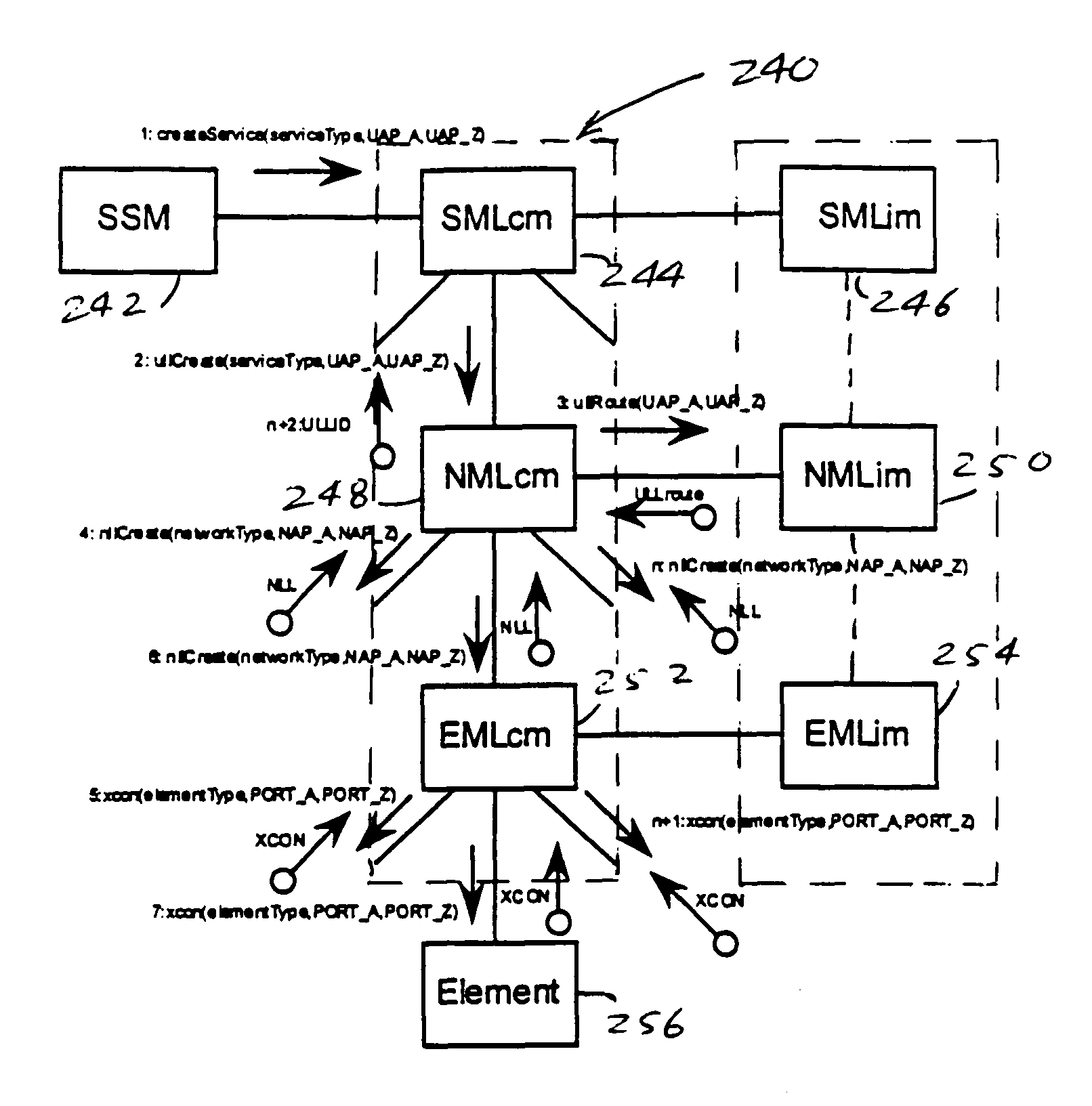
message diagram;

[0041]FIG. 18 shows a topology object diagram;

[0042]FIG. 19 shows a topology message diagram;

[0043]FIG. 20 is a screen display depicting a common desktop environment (CDE) menubar of a graphical user interface (GUI) for the Umbrella Management System (UMS);

[0044]FIG. 21 is a screen display depicting an application subpanel that is accessible through the menubar of FIG. 20;

[0045]FIG. 22 is a screen display depicting a provisioning tool, with the introduction tab in front, that is used to interface with the Umbrella Management System (UMS);

[0046]FIG. 23 is a screen display depicting the provisioning tool, with the provision tab in front, illustrating the selection of A and Z end points;

[0047]FIG. 24 is a screen display depicting the provisioning tool, with the topology tab in front, illustrating the Service Management Layer view of the A to Z connection;

[0048]FIG. 25 is a screen display depicting the Network Management Layer (NML) for the prototype implementation;

[0049...


PUM


Abstract

A network management system and graphical user interface for configuring a network connection between first and second service access points utilizes a configuration manager and information manager to provide a generic set of models so that different manufacturer's nodal processors and other network hardware can be inserted into the network with minimal changes to the software which controls the device. The system comprises an information manager including routing information for the network. The configuration manager operates to establish a connection across each subnet on the route by sending requests to element managers to program the subnet elements.

Description

CROSS-REFERENCE TO RELATED APPLICATIONS[0001]This application claims the benefit of U.S. Provisional application 60 / 114,424, filed on Dec. 31, 1998 and entitled “Scalable Service Selection for XDSL”, U.S. Provisional application No. 60 / 114,429, filed on Dec. 31, 1998 and entitled “Umbrella Management System User Guide,” U.S. Provisional application No. 60 / 114,428, filed on Dec. 31, 1998 and entitled “Umbrella Management System Prototype and Design,” and U.S. Provisional Application No. 60 / 114,427, filed on Dec. 31, 1998, and entitled “System and Method For Rapid Service Activation and Turn-up of XDSL.”TECHNICAL FIELD[0002]The present invention relates to a network management system for configuring a network connection between first and second service access points, to user interfaces for network management systems, and to online network management applications.BACKGROUND ART[0003]Existing network architectures, for a single network provider, include a plurality of subnetworks or sub...

Claims


Application Information

Patent Timeline
Patent Type & Authority Patents(United States)
IPC IPC(8): G06F15/173H04J3/22H04L12/26H04J3/16H04J3/14H04J1/16G06F15/16G06F15/177G01R31/08G06F9/46G06F11/00G08C15/00G06F9/00G06F9/24H04L1/00G06F3/14H04L12/24H04L12/56
CPCH04L12/24H04L41/00H04L41/0206H04L41/0806H04L45/42H04L41/22H04L45/00H04L41/0896H04L41/5003H04L41/5054H04L41/052
Inventor PUGACZEWSKI, JOHN T.KAYS, JEFFREY T.CHANTILOUPE, NICHOLAS P.HENDRICKS, FRED M.
Owner QWEST
Why Eureka
Try Eureka