Reverse-flow gas turbine combustion system

a gas turbine and combustion system technology, applied in the ignition of turbine/propulsion engines, engines/engines, machines/engines, etc., can solve the problems of high efficiency, low emissions, and catastrophic damage or acceleration of wear in current dry, and achieve the effects of low emissions, high efficiency, and high efficiency

Inactive Publication Date: 2011-06-28
GENERAL ELECTRIC CO
View PDF22 Cites 89 Cited by
  • Summary
  • Abstract
  • Description
  • Claims
  • Application Information

AI Technical Summary

Problems solved by technology

Known turbine engines have developed into highly complex and sophisticated devices.
Another issue with known gas turbine engines is promoting operation at high efficiency without producing undesirable air emissions.
Lean premixed combustors also have a susceptibility to dynamics that can cause catastrophic damage or accelerated wear in current dry, low emissions combustion systems.

Method used


Image

  • Reverse-flow gas turbine combustion system
  • Reverse-flow gas turbine combustion system
  • Reverse-flow gas turbine combustion system

Examples


Embodiment Construction

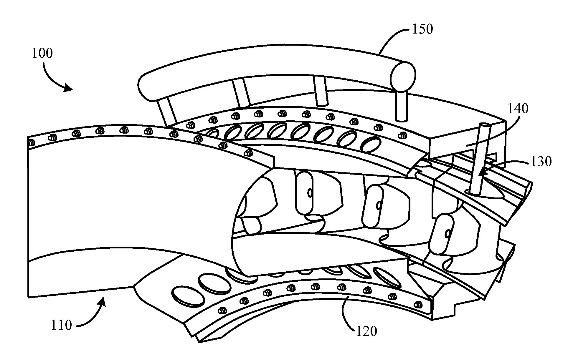
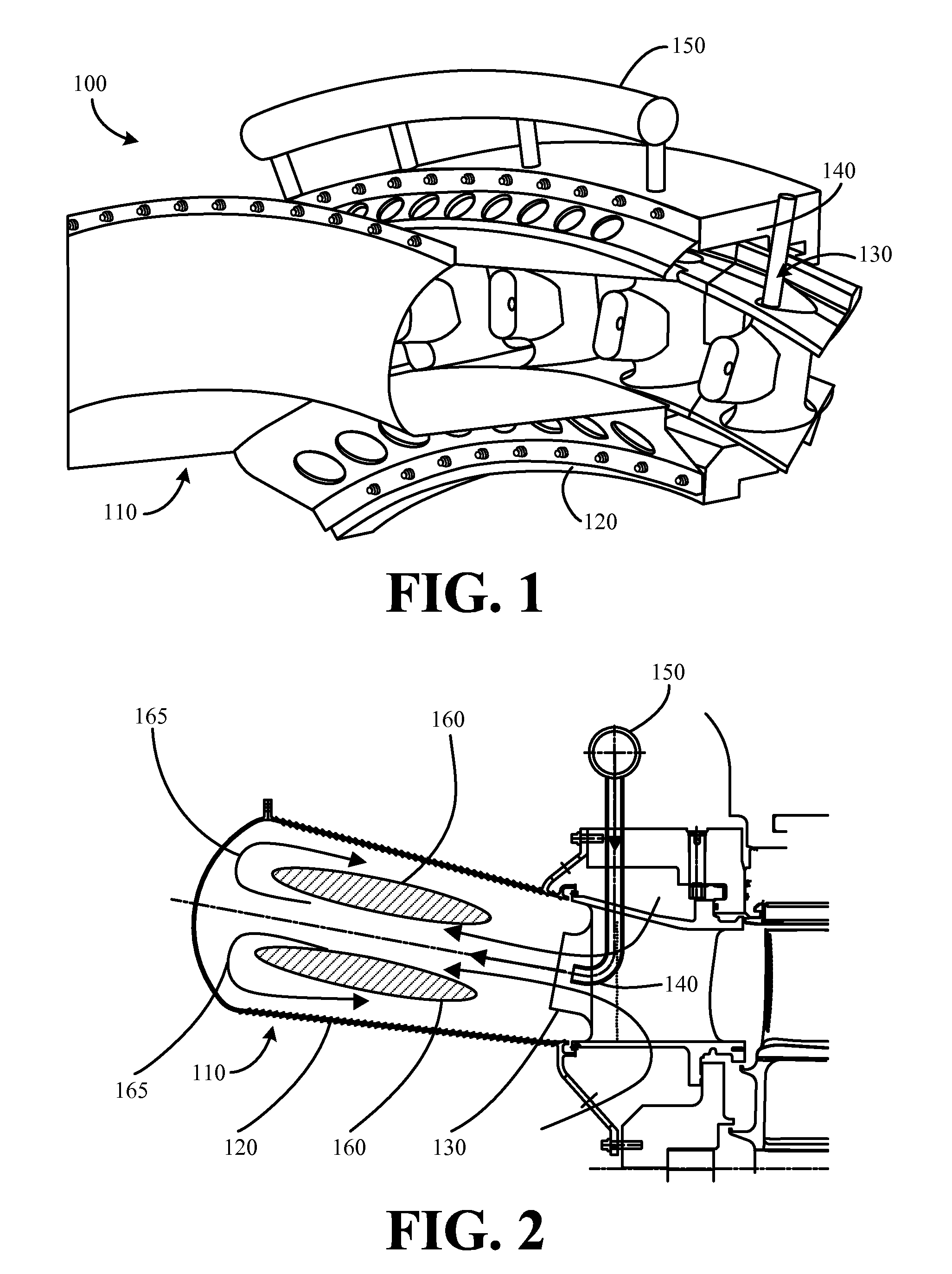
[0021]Referring now to the drawings, in which like numerals refer to like elements throughout the several views, FIGS. 1 and 2 show a combustion system 100 as is described herein. The combustion system 100 includes a combustor 110. As will be described in more detail below, the combustor 110 may be a reverse flow annular combustor. The combustor 110 includes an annular combustor liner 120. The liner 120 shapes the flow field to provide the reverse flow.

[0022]The combustion system 100 includes a turbine nozzle 130 that is integral with the combustor 110. In this example, the turbine nozzle 130 is a stage-one nozzle. Other designs also may be used herein. The turbine nozzle 130 supplies air for combustion and for cooling. The nozzle 130 also may be cooled via a flow of the fuel.

[0023]The combustion system 100 further includes a fuel injector 140. In this example, the fuel injector 140 is positioned within the turbine nozzle 130 and is integral therewith. The fuel injector 140 may be i...


PUM


Abstract

A gas turbine combustion system for burning air and fuel into exhaust gases. The gas turbine combustion system may include a combustor, a turbine nozzle integral with the combustor for providing the air to the combustor, and a fuel injector for providing the fuel to the combustor. The turbine nozzle and the fuel injector are positioned within the combustor such that a mixture of the air and the fuel flows in a first direction and the exhaust gases flow in a second direction.

Description

TECHNICAL FIELD[0001]The present invention relates generally to gas turbine combustion engines and relates more particularly to a reverse-flow gas turbine combustion system with an integral first stage turbine nozzle.BACKGROUND OF THE INVENTION[0002]Generally described, gas turbine engines include a compressor for compressing air, a combustor for mixing the compressed air with fuel and igniting the mixture, and a turbine blade assembly for producing power. Known turbine engines have developed into highly complex and sophisticated devices. For example, known turbine combustor systems alone may require more than 14,000 parts.[0003]Another issue with known gas turbine engines is promoting operation at high efficiency without producing undesirable air emissions. The primary air emissions usually produced by gas turbine engines include nitrogen oxides (NOx). Lean premixed combustors also have a susceptibility to dynamics that can cause catastrophic damage or accelerated wear in current d...

Claims


Application Information

Patent Timeline
Patent Type & Authority Patents(United States)
IPC IPC(8): F02C1/00
CPCF02C3/145
Inventor MYERS, GEOFFREY DAVIDJOHNSON, THOMAS EDWARDMAIER, STEFANWIDENER, STANLEY KEVIN
Owner GENERAL ELECTRIC CO
Why Eureka
Try Eureka