Rolling bearing unit for rotation support unit

a technology of rotating support unit and rolling bearing, which is applied in the direction of bearing unit rigid support, shaft assembly, mechanical apparatus, etc., can solve the problems of increasing cost and inevitable cost, and achieve the effect of low cos

Inactive Publication Date: 2011-06-28
NSK LTD
View PDF9 Cites 10 Cited by
  • Summary
  • Abstract
  • Description
  • Claims
  • Application Information

AI Technical Summary

Benefits of technology

[0012]This invention has been made in view of the above circumstances, and an object of the invention is to provide a rotation support unit and a rolling bearing unit for a rotation support unit, in which a structure of combination of an outer ring of a rolling bearing and a retainer plate for retaining the outer ring in a holding recess can be easily obtained at a low cost.
[0020]wherein the retainer plate is disposed between the step surface of the outer ring and the larger-diameter retaining portion of the retaining ring so as to rotate relative to the smaller-diameter step portion of the outer ring and so as to prevent the retainer plate from falling off therefrom to the other axial end side.
[0061]With the above construction of the rolling bearing unit of the invention for the rotation support unit, the structure of combination of the outer ring of the rolling bearing and the retainer plate for retaining the outer ring in the holding recess can be easily obtained within low cost.
[0062]Namely, the retaining ring for connecting the outer ring and the retainer plate together can be easily formed by bending a resilient metal wire or by injection molding a synthetic resin. In addition, the retaining recessed groove for retaining the retaining ring can be easily formed in the outer circumferential surface of the smaller-diameter step portion of the outer ring by a simple lathe turning operation. Furthermore, the recess portions and the retaining projections can be easily formed at the inner circumferential surface of the fitting hole of the retainer plate by press working. Therefore, the above structure can be easily obtained at the low cost as described above.

Problems solved by technology

In the, structure described in DE 102005012323B3, although such a disadvantage is not encountered, the cost is inevitably increased since the leaf spring complicated in shape and requiring cumbersome processing or working is used.
Further, in the structure described in JP-T-2007-504412, a pressing machine for plastically deforming the retainer plate is required, and therefore the cost is increased.

Method used


Image

  • Rolling bearing unit for rotation support unit
  • Rolling bearing unit for rotation support unit
  • Rolling bearing unit for rotation support unit

Examples


first embodiment

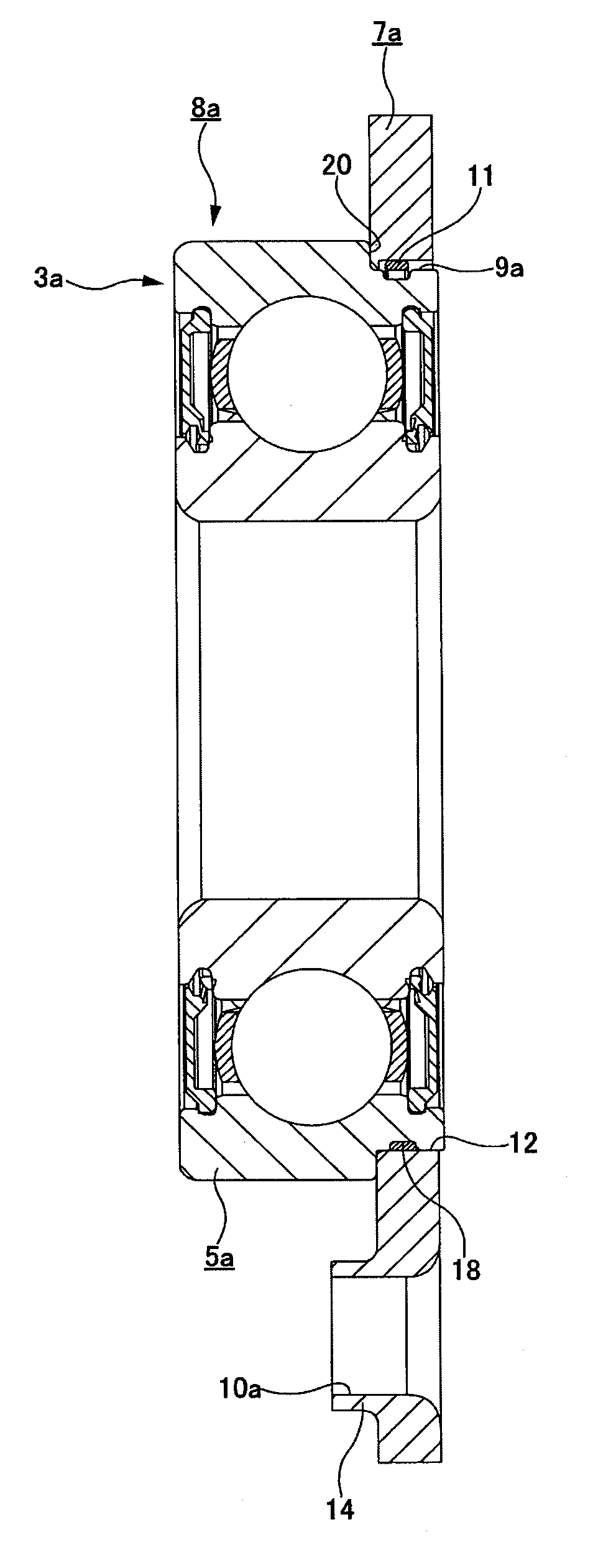
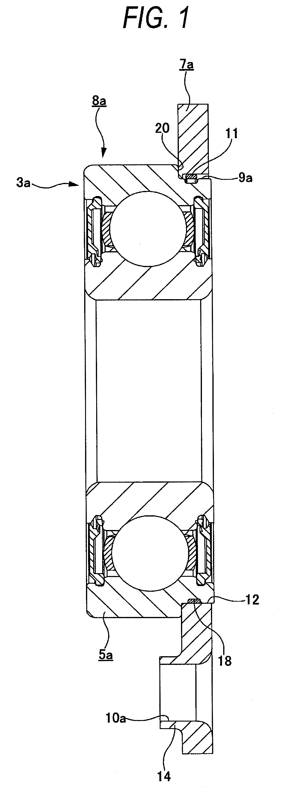
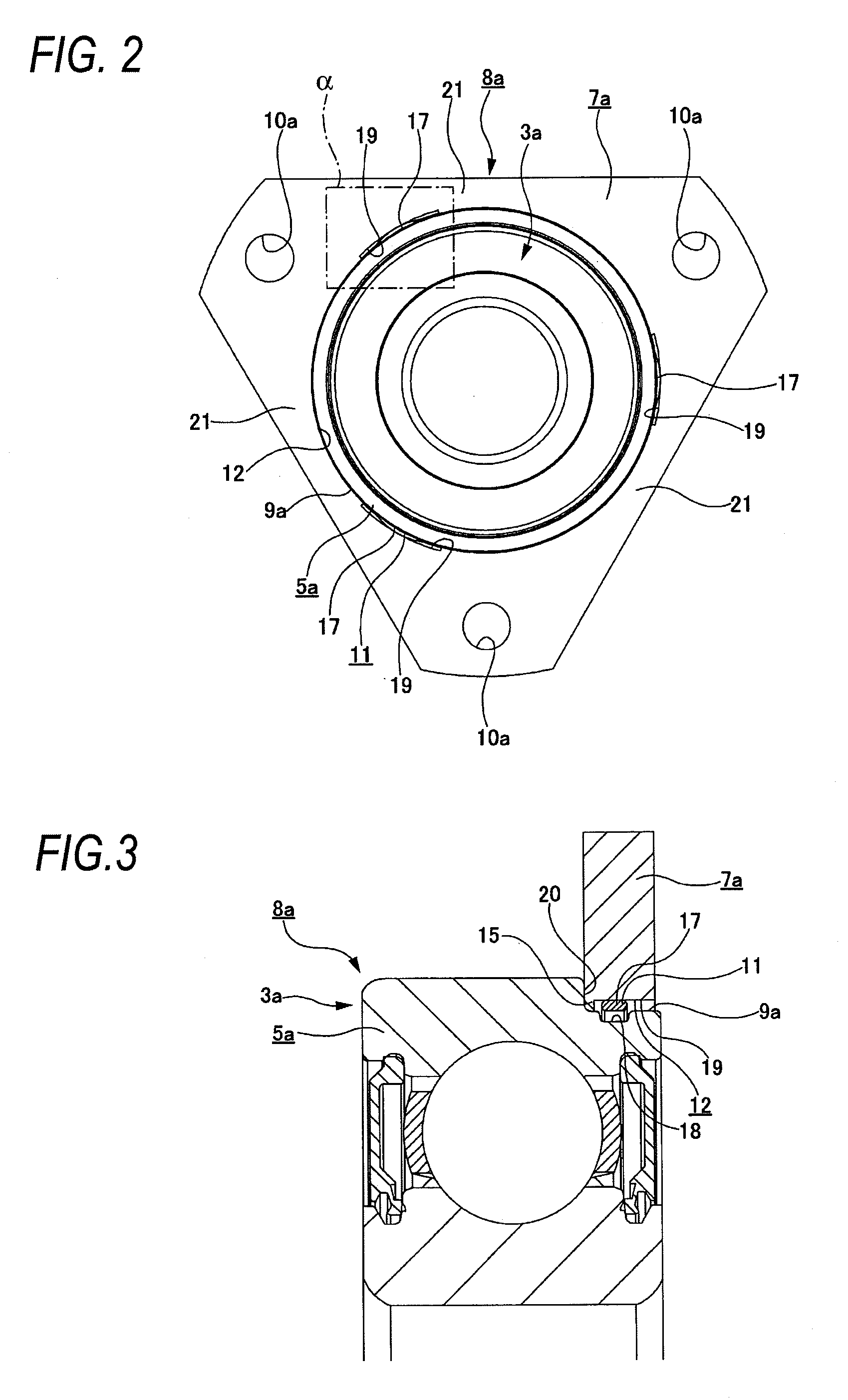
[0099]FIGS. 1 to 12 shows a first embodiment of the present invention. As shown in FIGS. 1 to 4, the rolling bearing unit 8a of this embodiment includes a retainer plate 7a which is connected to an outer ring 5a of a rolling bearing 3a through a retaining ring 11 in such a manner that the retainer plate 7a can rotate relative to the outer ring 5a but can not be separated therefrom. This rolling bearing unit 8a is used to rotatably support an end portion of the rotation shaft 1 on the inner surface of the housing 2 of an automatic transmission as shown in FIG. 30. The rolling bearing unit 8a is mounted between the housing 2 and the rotation shaft 1 in the same manner as described above for the conventional structure of FIG. 30, and the basic structure and operation of the rolling bearing 3a are the same as those of a single row deep groove ball bearing, and therefore description thereof will be omitted or given briefly, and the structure of the connecting portion between the outer ri...

second embodiment

[0114]FIG. 13 shows a second embodiment of the invention. In this embodiment, except for a region where a retaining projection 15a which is described later, an inner diameter of a fitting hole 12a formed through a central portion of a retainer plate 7b is sufficiently larger than an outer diameter of a smaller-diameter step portion 9a (on which the retainer plate 7b to be fitted and supported) formed on an outer circumferential surface of an end portion of an outer ring 5a (that is, larger than a circle circumscribing larger-diameter retaining portions 17 of a retaining ring 11). The retaining projection 15a is formed on one axial end of the inner circumferential surface of the fitting hole 12a over the entire periphery thereof, and projects radially inwardly from the inner circumferential surface of the fitting hole 12a. The basic shape of the retaining projection 15a is similar to that of the retaining projections 15 (see FIGS. 3, 4, 9, 11 and 12) of the above first embodiment.

[01...

third embodiment

[0117]FIG. 14 shows a third embodiment of the invention. An inner circumferential surface of a retaining projection 15b formed on an inner circumferential surface of a fitting-hole 12b formed through a central portion of a retainer plate 7c is formed by an inclined surface 22 and a concave cylindrical surface 23. The inclined surface 22 is formed at one axial end portion of the inner circumferential surface of the retaining projection 15b, and has a conical concave shape of which inner diameter increases toward the one axial end. When the fitting hole 12b is outwardly fitted on a smaller-diameter step portion 9a, the inclined surface 22 is disposed on one axial end portion of this smaller-diameter step portion 9a. The concave cylindrical surface 23 is formed on the other axial end portion of the inner circumferential surface of the retaining projection 15b, and the inner diameter thereof is constant along with the axial direction. When the fitting hole 12b is fitted on the smaller-d...


PUM


Abstract

A retainer plate 7a is fitted on a smaller-diameter step portion 9a of an outer ring 5a, and a retaining ring 11 fitted on the smaller-diameter step portion 9a is engaged with retaining projections 15 formed on an inner circumferential surface of a fitting hole 12 formed through the retainer plate 7a, thereby preventing the retainer plate 7a from falling-off from the smaller-diameter step portion 9a. The structures and shapes of the various portions are so determined that working or machining can be easily effected to form these portions so as to overcome a problem encountered with the conventional structure.

Description

BACKGROUND OF THE INVENTION[0001]1. Field of the Invention[0002]This invention relates to an improved rolling bearing unit which is a part of a rotation support unit (for example, a manual transmission or an automatic transmission of an automobile transmission) for supporting an end portion of a rotation shaft on an inner surface of a housing containing component parts of the automobile transmission.[0003]2. Description of the Related Art[0004]As shown in FIG. 30, an end portion of a rotation shaft 1 such as a counter shaft of an automobile transmission is rotatably supported on an inner surface of a housing 2 accommodating components such as the rotation shaft 1, a gear, etc., through a rolling bearing 3 such as a ball bearing. In this case, an annular or circular holding recess 4 is formed in the inner surface of the housing 2, and an outer ring 5 of the rolling bearing 3 is fitted in the holding recess 4 to be inwardly fixed thereto in an interference manner. The end portion of t...

Claims


Application Information

Patent Timeline
Patent Type & Authority Patents(United States)
IPC IPC(8): F16C43/00
CPCF16C35/077F16C33/586F16C35/045F16C2226/72F16C2226/74Y10S384/903F16C19/06F16C35/067F16C2226/50F16C2226/60F16C2361/61
Inventor HIMEDA, DAISUKEKATOUGI, TAKAOSUGIMAN, TOMOHARUHONDA, TOSHIHARUHARADA, JUJIURAKAMI, SEIGOUKATO, TAKASHI
Owner NSK LTD
Why Eureka
Try Eureka