
Vascular fluoroscopic marker

a fluoroscopic marker and vascular technology, applied in the field of radiopaque markers, can solve the problems of reducing and affecting the normal dilation of the vessel wall, so as to reduce the diameter of the radiopaque marker ring

Active Publication Date: 2011-06-28
MEDTRONIC VASCULAR INC
View PDF7 Cites 10 Cited by
  • Summary
  • Abstract
  • Description
  • Claims
  • Application Information

AI Technical Summary

Benefits of technology

[0014]In one embodiment according to the invention, a method of securing a radiopaque marker to a tubular member adapted for introduction into a patient, comprises sliding a radiopaque marker ring over a tubular member adapted for introduction into a human patient; and reducing the diameter of the radiopaque marker ring without wrinkling the marker.

Problems solved by technology

The abnormally dilated vessel has a wall that typically is weakened and susceptible to rupture.
Although the endovascular approach is much less invasive, and usually requires less recovery time and involves less risk of complication as compared to open surgery, one challenge of this approach is positioning the catheter at the desired site.
These bands typically are not compressed onto the tubular catheter to secure it to the catheter as the band can wrinkle or kink, which can result in an undesirable increase in profile.
However, one drawback associated with using such a metal powder based ring is that the metal powder can cause degradation of the native polymer of the band and adversely impact its strength as it ages.

Method used


Image

  • Vascular fluoroscopic marker
  • Vascular fluoroscopic marker
  • Vascular fluoroscopic marker

Examples


Embodiment Construction

[0028]The following description will be made with reference to the drawings where when referring to the various figures, it should be understood that like numerals or characters indicate like elements.

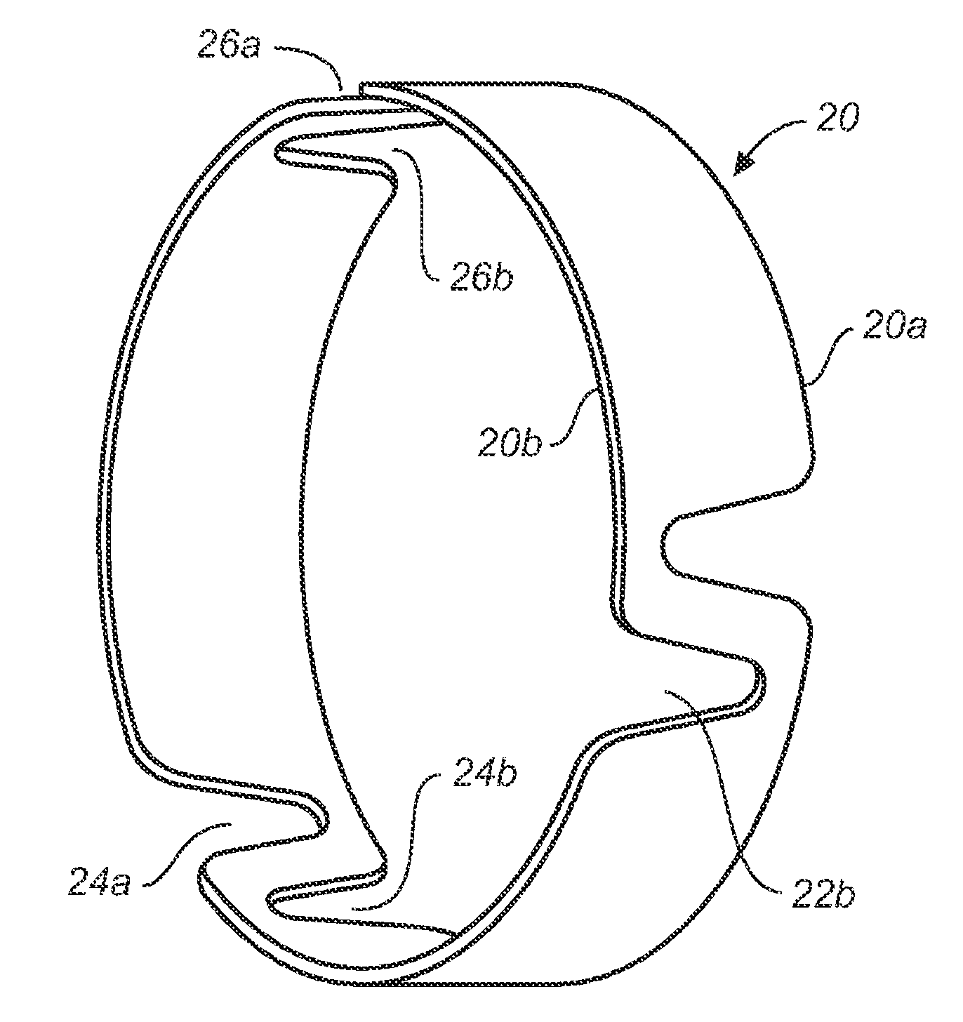
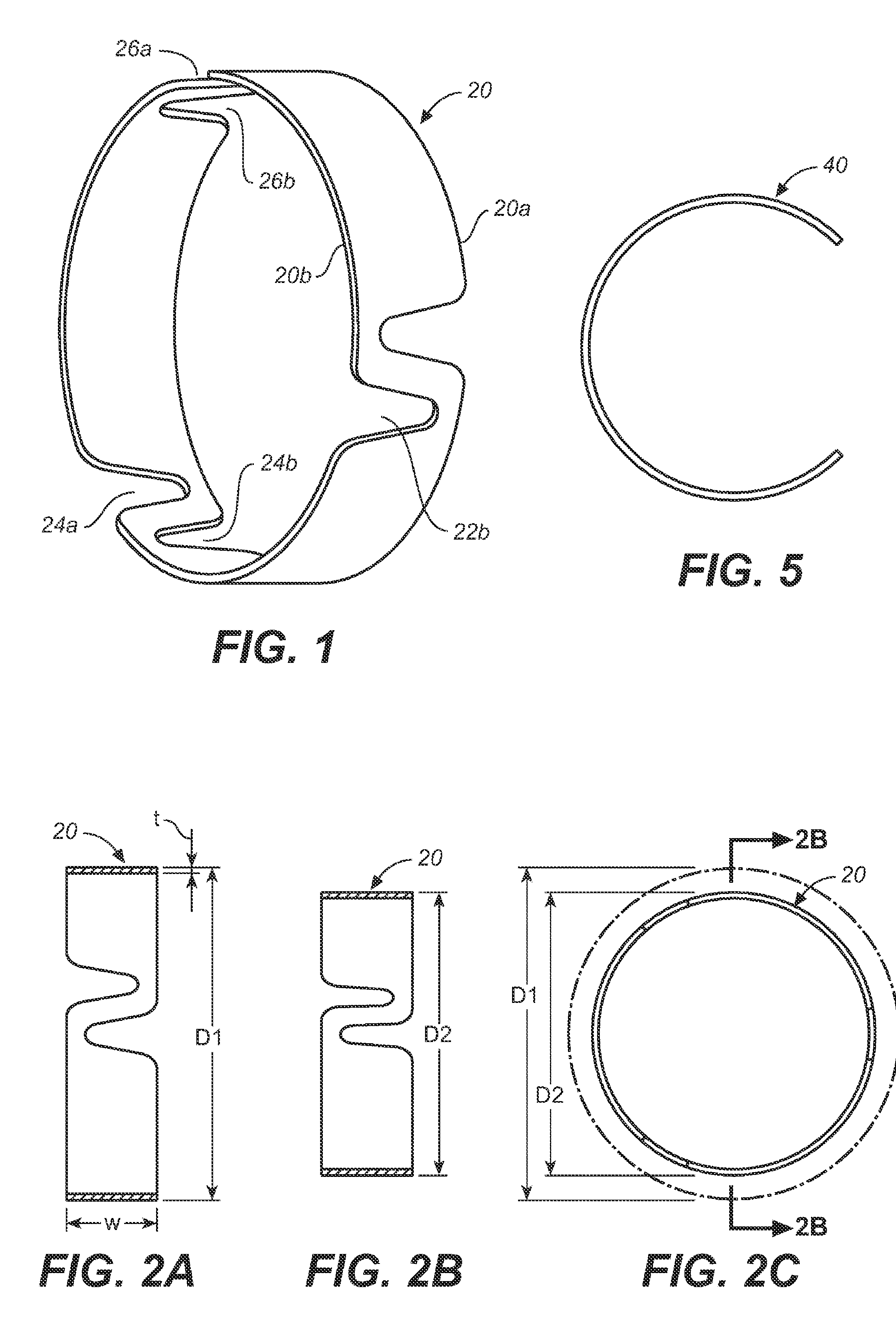
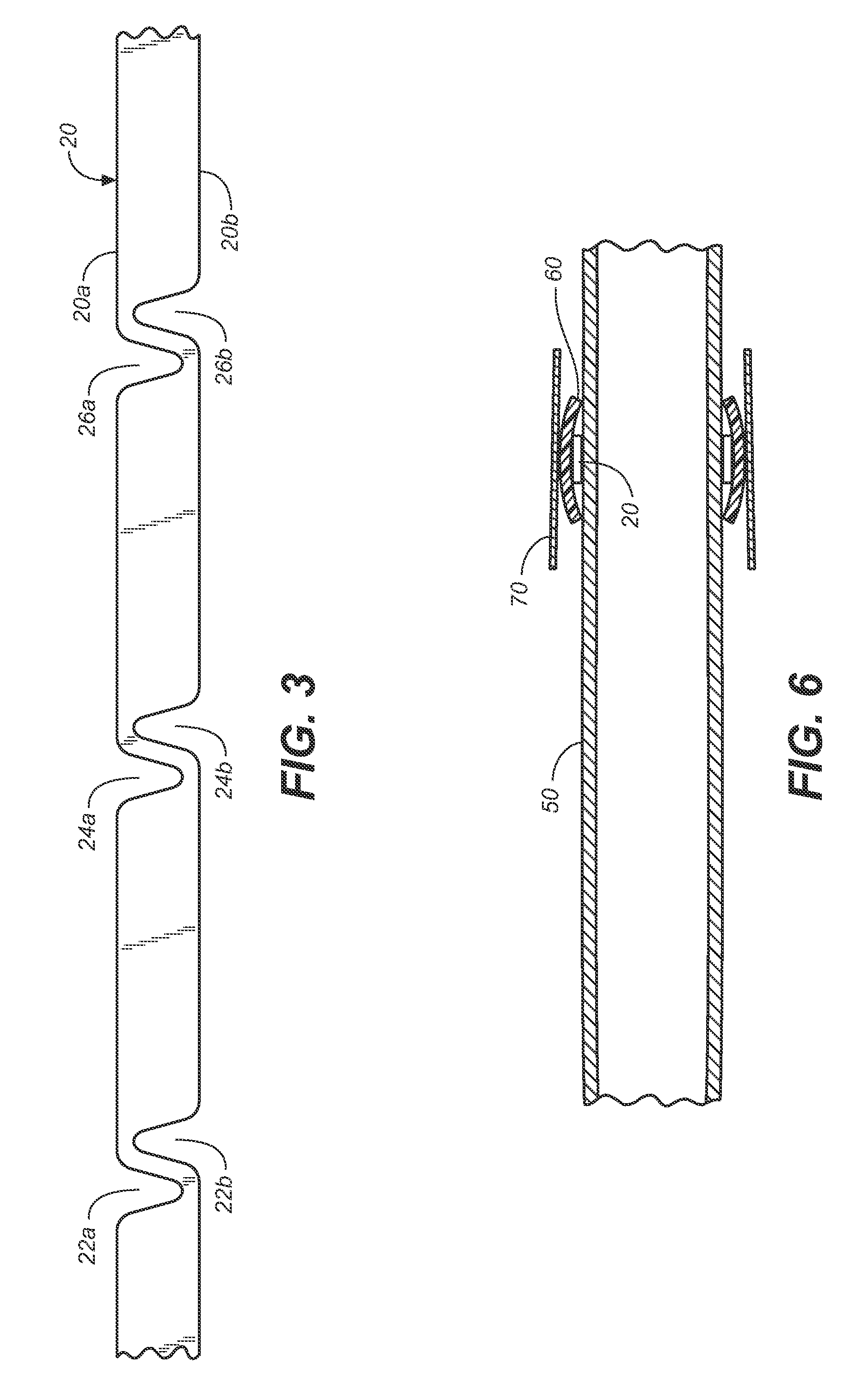
[0029]According to various embodiments of the invention, a marker, which can be in the form of a band, is provided with a construction to facilitate its securement to a tube or lumen that is configured for introduction into a patient. The marker is constructed to allow its radial compression and / or diametrical reduction over a tube or lumen, while minimizing or eliminating the risk of it kinking or wrinkling. The marker can have relief sections for accommodating a reduction in its diameter or circumference. In one example, the marker can include one or more cut-outs to allow diametrical or circumferential reduction when subjected to radial compression. In the case where a plurality of cut-outs are used, they can be asymmetrically or symmetrically arranged.

[0030]The tube or lumen to whi...


PUM


Abstract

A radiopaque marker configured for being securing to a tubular member adapted for introduction into a patient and having relief sections to provide localized accommodation of diametrical-circumferential dimensional reduction.

Description

FIELD OF THE INVENTION[0001]The invention relates to several specific configurations of a radiopaque marker that can be applied to a tubular member for assisting in visualizing the position of the tubular member in a patient.BACKGROUND OF THE INVENTION[0002]Fluoroscopic markers (markers which are clearly identifiable under fluoroscopy) have been used on tubular devices for various medical procedures to facilitate imaging and / or tracking a portion of the tubular member in a patient. This can assist a physician with delivery of the tubular device, which can be a catheter or the like.[0003]For example, fluoroscopic markers have been used on catheters that are designed for delivering tubular prosthesis. Tubular prostheses such as stents, grafts, and stent-grafts (e.g., stents having an inner and / or outer covering comprising graft material and which may be referred to as covered stents) have been widely used in treating abnormalities in passageways in the human body. In vascular applicat...

Claims


Application Information

Patent Timeline
Patent Type & Authority Patents(United States)
IPC IPC(8): A61M25/098
CPCA61F2/04A61F2250/0098A61F2/07
Inventor MURRAY, ROBERT
Owner MEDTRONIC VASCULAR INC
Learn More