Ceramic substrate production process and ceramic substrate produced using the process

a ceramic substrate and production process technology, applied in the field of ceramic substrate production process, can solve the problems of increased production cost and difficulty in maintaining the required degree of dimensional precision, and achieve the effects of reducing deformation angle, reducing production cost, and reducing production cos

Inactive Publication Date: 2011-06-28
MURATA MFG CO LTD
View PDF13 Cites 4 Cited by
  • Summary
  • Abstract
  • Description
  • Claims
  • Application Information

AI Technical Summary

Benefits of technology

[0039]Dies each having the projection are preferably arranged to face a predetermined position on each of the two principal surfaces of the auxiliary-layer-lined unfired ceramic body, whereby step portions having shapes corresponding to the external shapes of the associated dies are formed in both principal surfaces of the auxiliary-layer-lined unfired ceramic body. With this process, it is possible to securely form sharp step portions on both sides of the product, corresponding to the contours of the die projections, thus enhancing the advantageous effects of various preferred embodiments of the present invention.
[0040]The projection of the die preferably has a plurality of steps, so that the step portion is formed in the auxiliary-layer-lined unfired ceramic body to have a shape corresponding to an outer shape of the projection having the plurality of the steps. This process offers a greater versatility in the shape of the step portions, thus making it possible to efficiently produce ceramic substrates having various shapes of step portions adapting to a wide use.
[0041]A tapered die projection is preferably used in the ceramic substrate production process. The use of a die having a tapered die projection makes it possible to reduce a deformation angle at the step portion, as compared to the case where a die has a projection of another shapes, e.g., a quadratic prism or a cylindrical shape. This enables production of an unfired ceramic body having a step portion of a desired depth, while suppressing or eliminating breakage and rupture of the unfired ceramic body and internal electrode pattern provided therein, even when the depth of the step portion is large.
[0042]It is to be understood that the allowance for the increased depth of the step portion affords a greater versatility in the dimensions of the step portion.
[0043]At least the projection of the die preferably has a hardness that is greater than those of the unfired ceramic body and the auxiliary layer constituting the auxiliary-layer-lined unfired ceramic body and also has elasticity. This ensures that a step portion having a shape corresponding to the shape of the die projection is formed in the unfired ceramic body, thus enhancing the advantageous effects of various preferred embodiments of the present invention.
[0044]By way of example, the following method can be used for forming a die projection which has hardness greater than those of the unfired ceramic body and the auxiliary layer constituting the auxiliary-layer-lined unfired ceramic body and which also has elasticity. A green sheet (auxiliary layer green sheet) is formed by compounding a powder used as the material of the auxiliary layer (other type of powder also may be used) with a binder and forming the compound into a sheet. Then, the green sheet is punched to form a green sheet (die-forming green sheet) in which only the portions to form the projection are left unremoved. A plurality of such die-forming green sheets are then stacked and press-bonded under a load of a level which is the same as the load applied when forming the auxiliary-layer-lined unfired ceramic body by laminating and press-bonding substrate forming green sheets and auxiliary layer green sheets. The die-forming green sheets have vacant areas which have been punched out. The pressure received by a unit area is therefore greater when the die-forming green sheets are press-bonded, as compared to the pressure applied to the same unit area in the press-bonding of the substrate forming green sheets and auxiliary layer green sheets, even though the level of the pressing load is equal. It is thus possible to form a die having a projection which has hardness greater than those of the unfired ceramic body and the auxiliary layer constituting the auxiliary-layer-lined unfired ceramic body and which also has elasticity.

Problems solved by technology

This process, however, requires laborious work for punching ceramic sheets and, in addition, a complicated process for performing press-bonding to be conducted prior to firing, resulting in an increased production cost.
Another problem is that it is not easy to maintain the required degree of dimensional precision due to influence of undulation encountered in the course of firing.

Method used


Image

  • Ceramic substrate production process and ceramic substrate produced using the process
  • Ceramic substrate production process and ceramic substrate produced using the process
  • Ceramic substrate production process and ceramic substrate produced using the process

Examples


first preferred embodiment

[0085]A description will be given of a first preferred embodiment of a ceramic substrate production process of the present invention.

[0086](1) First, ceramic green sheets (hereinafter referred to as “substrate green sheets”) containing a ceramic material used for forming a ceramic substrate are prepared. An example of the procedure is as follows.

[0087]A mixture containing about 5% to about 20% by weight of B2O3 with respect to a sub-mixture composed of about 10% to about 55% percent by weight of CaO, about 45% to about 70% by weight of SiO2, about 0% to about 30% percent by weight of Al2O3 and about 0% to about 10% percent by weight of impurities is vitrified by melting at approximately 1,450° C. and is then quenched in water, followed by pulverization, so that a powdered CaO—SiO2—Al2O3—B2O3-based glass having an average grain size of about 3.0 μm to about 3.5 μm is formed.

[0088]In this first preferred embodiment, although CaO—SiO2—Al2O3—B2O3-based glass was preferably used, other t...

second preferred embodiment

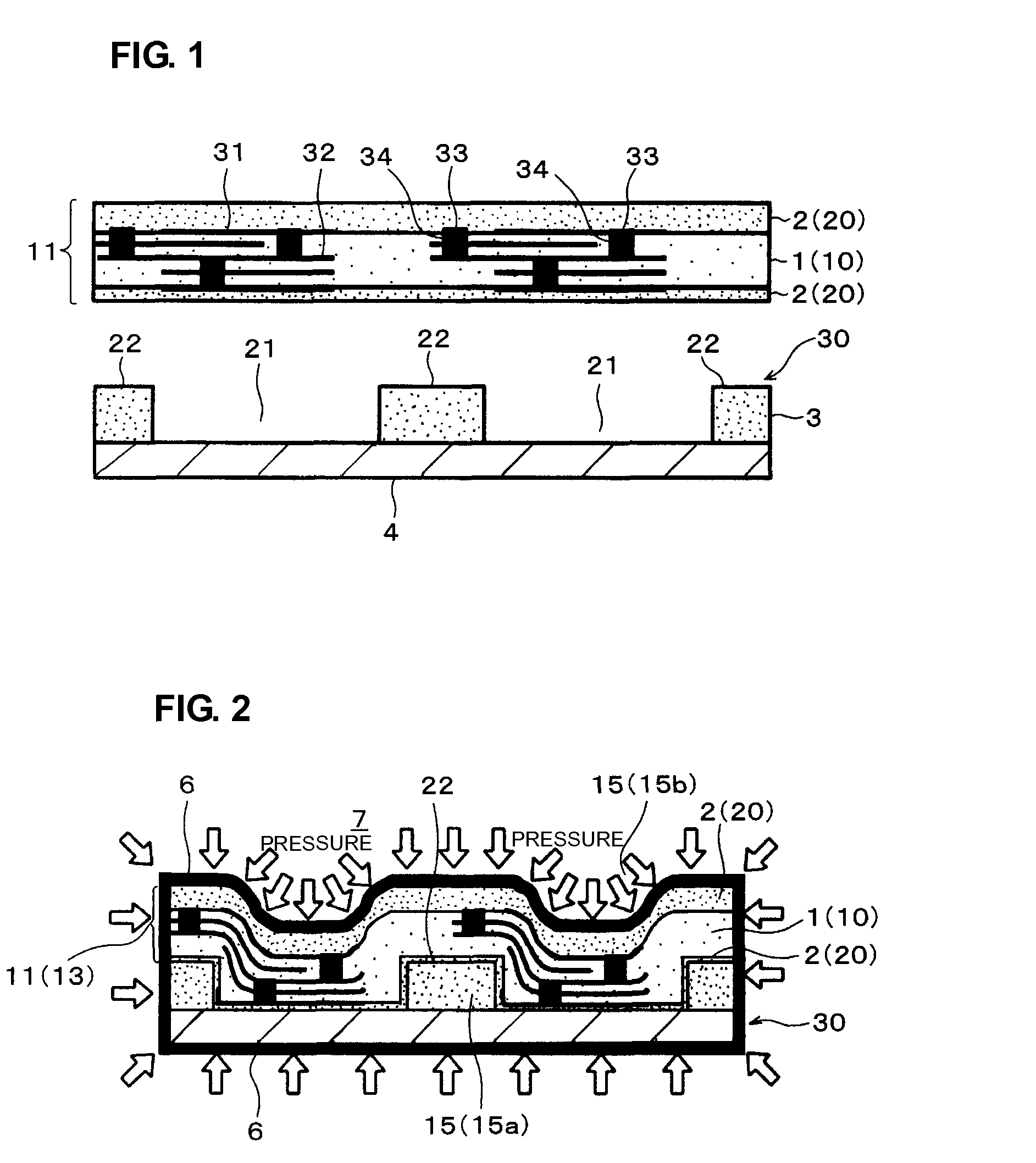
[0130]FIG. 9 shows one step of a ceramic substrate production process of another preferred embodiment.

[0131]In FIG. 9, elements designated by the same reference numerals as those in FIGS. 1 and 2 indicate elements which are the same as or corresponding to those shown therein.

[0132]The second preferred embodiment preferably uses, as the pressing (deforming) die, a die 30 which is formed by directly forming recesses 21 and projections 22 having predetermined shapes on a plate 4 made of a material having an appropriate level of hardness (preferably resin in this preferred embodiment). Other features are similar to those of the first preferred embodiment.

[0133]The above-mentioned resin-made die is only illustrative, and a die formed by providing recesses and projections in a metal plate may also be used.

[0134]By using the die 30 as shown in FIG. 9, as in the case of the above-described first preferred embodiment, a ceramic substrate is produced through a step of forming a press-bonded m...

third preferred embodiment

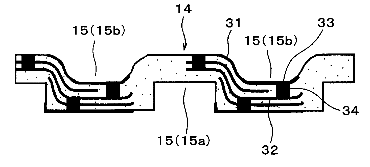
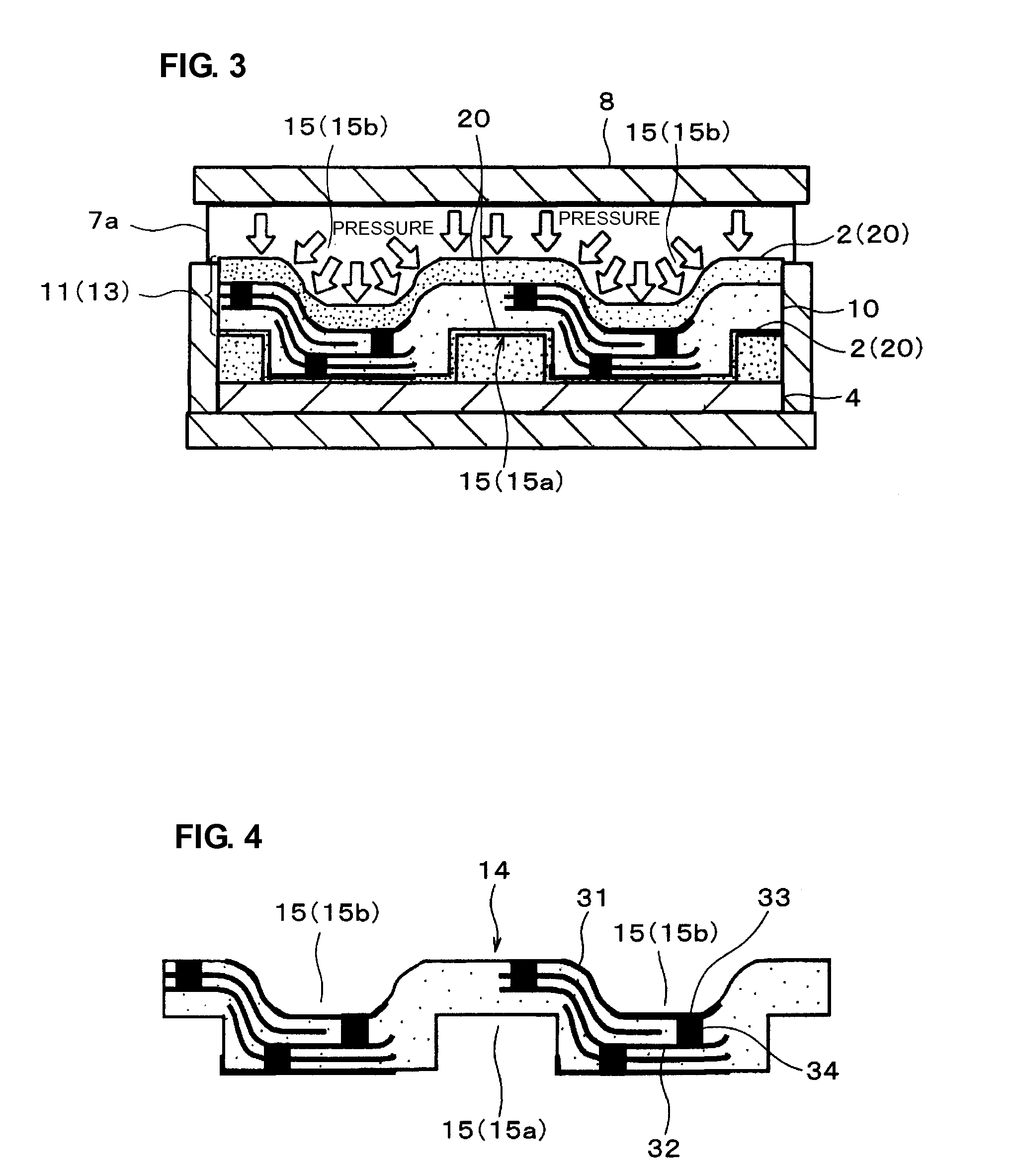
[0144]FIG. 10 shows one step of a ceramic substrate production process in accordance with still another preferred embodiment of the present invention.

[0145]In FIG. 10, elements designated with the same reference numerals as those in FIGS. 1 and 2 indicate elements which are the same as or corresponding to those shown therein.

[0146]In the third preferred embodiment, as is the case of the die 30 of the foregoing first preferred embodiment, a die 30 is used which is formed by adhering to a plate 4 die-forming green sheets 3, which are obtained by punching out sheets which are the same as auxiliary layer (constraining layer) green sheets 2 into a predetermined shape. Onto this die 30, sequentially formed and press-bonded by a so-called sequential press-bonding laminating method are predetermined numbers of auxiliary layer (constraining layer) green sheets 2 that are unsinterable at the sintering temperature of a substrate green sheet, substrate green sheets 1 for forming a ceramic subst...


PUM

PropertyMeasurementUnit
grain sizeaaaaaaaaaa
temperatureaaaaaaaaaa

Abstract

An auxiliary-layer-lined unfired ceramic body, having a step portion in a principal surface thereof, has an unfired ceramic body and an auxiliary layer which is adhered to one principal surface of the unfired ceramic body and which is made of a material that is substantially unsinterable at a temperature at which the unfired ceramic body is fired. The auxiliary-layer-lined unfired ceramic body is fired at a temperature at which the unfired ceramic body is sinterable but the auxiliary layer is substantially unsinterable, while the auxiliary layer remains adhered to the unfired ceramic body. A pressing operation is performed using a die having a projection placed on the side of the auxiliary-layer-lined unfired ceramic body retaining the auxiliary layer, so that the step portion, having a shape corresponding to the outer shape of the die projection, is formed in the side of the auxiliary-layer-lined unfired ceramic body retaining the auxiliary layer.

Description

BACKGROUND OF THE INVENTION[0001]1. Field of the Invention[0002]The present invention relates to a process for producing a ceramic substrate, and more particularly, to a ceramic substrate production process for producing a ceramic substrate having a step portion on at least one principal surface thereof, and also to a ceramic substrate produced by using the process.[0003]2. Description of the Related Art[0004]Ceramic substrates having step portions (typically, a cavity) provided on the surfaces thereof are known.[0005]A process has been proposed in Japanese Unexamined Patent Application Publication No. 3-169097 for producing this type of ceramic substrate in which, as shown in FIGS. 26A, 26B, and 26C, a multilayered ceramic substrate having a step portion (cavity) is produced by superposing second ceramic sheets 52, each having an opening portion 53, on first ceramic sheets 51, followed by press-bonding, to thereby form a laminate structure 57. In this process, a plate member 54 (in...

Claims


Application Information

Patent Timeline
Patent Type & Authority Patents(United States)
IPC IPC(8): C04B33/32
CPCB32B18/00H05K1/183H05K3/0014H05K3/4697C04B35/63C04B35/6342C04B35/63424Y10T156/10C04B2237/56C04B2237/64H05K1/0284H05K1/0306H05K3/4611H05K3/4629H05K2203/0108H05K2203/0113C04B2235/656C04B2237/32C04B2237/343C04B2237/68C04B2237/704C04B2237/86C04B2237/50C04B35/64H05K3/46
Inventor ITO, YUKICHIKAGAWA, OSAMUIKEDA, TETSUYA
Owner MURATA MFG CO LTD
Why Eureka
Try Eureka