
Block switching transient minimization for linear motors and inductive loads

a linear motor and block switching technology, applied in the field of linear motors, can solve the problems of affecting the performance of the motor, upset the smooth operation, and prior work on linear motor systems does not address the practical problems of linear motor block switching, so as to reduce the generation of undesirable transient behavior, minimize the transient frequency and severity, and reduce the effect of block switching

Active Publication Date: 2011-06-28
ELECTRO STANDARDS LAB
View PDF7 Cites 15 Cited by
  • Summary
  • Abstract
  • Description
  • Claims
  • Application Information

AI Technical Summary

Benefits of technology

The solution significantly reduces the frequency and severity of block switching transients, ensuring smooth operation and extending the lifespan of components in high-power applications by accurately synchronizing switch activation with current zero crossings and applying closed-loop control to suppress residual transients.

Problems solved by technology

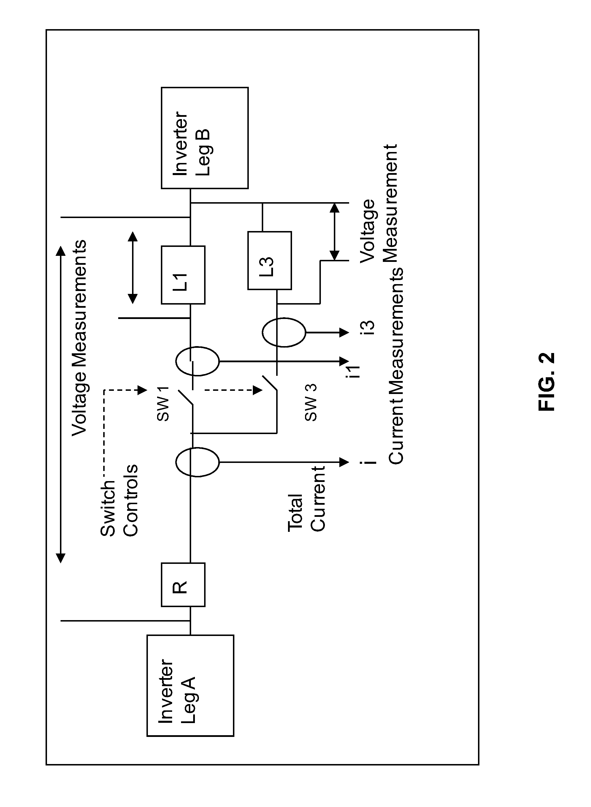
Switching inductive motor blocks in and out of the circuit as the shuttle travels along the track creates transient conditions that can affect motor performance.
Two main areas of concern are transient saturation of the core as the new coil is engaged and transient load imbalance.
These effects can result in transient current surges that lead to component damage and transient forces that upset smooth operation.
Prior work on linear motor systems does not address the practical issues of linear motor block switching.
These prior art systems require long wires carrying power that are attached to the moving shuttle and eventually wear down due to mechanical stress.
Neither of these architectures is suitable for use in a high power, high acceleration application, such as an electromagnetic aircraft launch system (EMALS) application.

Method used


Image

  • Block switching transient minimization for linear motors and inductive loads
  • Block switching transient minimization for linear motors and inductive loads
  • Block switching transient minimization for linear motors and inductive loads

Examples


Embodiment Construction

[0062]While this invention is illustrated and described in a preferred embodiment, the invention may be produced in many different configurations. There is depicted in the drawings, and will herein be described in detail, a preferred embodiment of the invention, with the understanding that the present disclosure is to be considered as an exemplification of the principles of the invention and the associated functional specifications for its construction and is not intended to limit the invention to the embodiment illustrated. Those skilled in the art will envision many other possible variations within the scope of the present invention.

1.0 Analysis of Block Switching Transients Problem

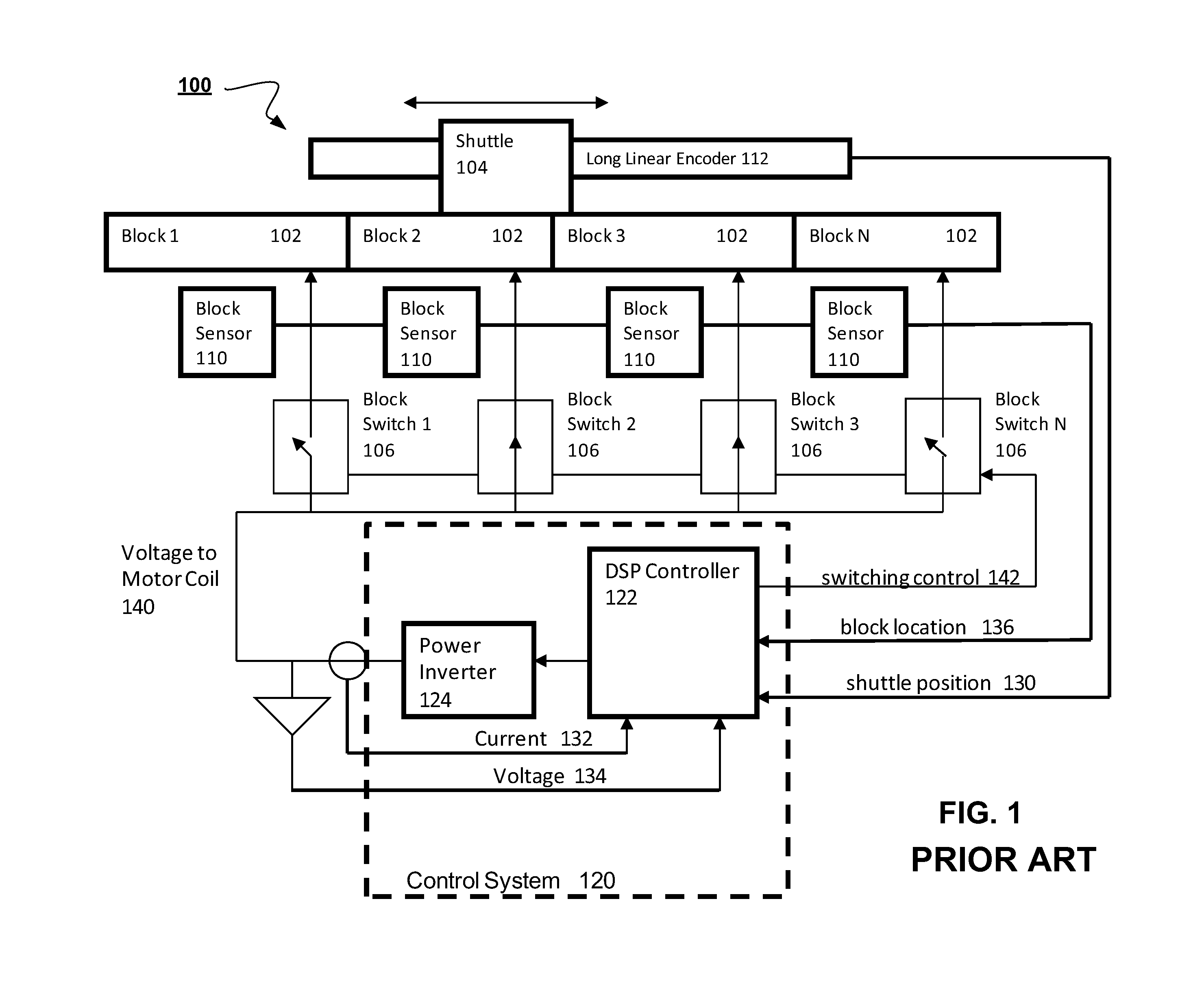
[0063]Referring to FIG. 1, as the shuttle moves along its stroke from block 2 to block 3, block switch 1 is turned off and block switch 3 is turned on, while block switch 2 remains on. The steady state result is that current flows in block 2 and block 3 and the motor's force is relatively constant. The ...


PUM


Abstract

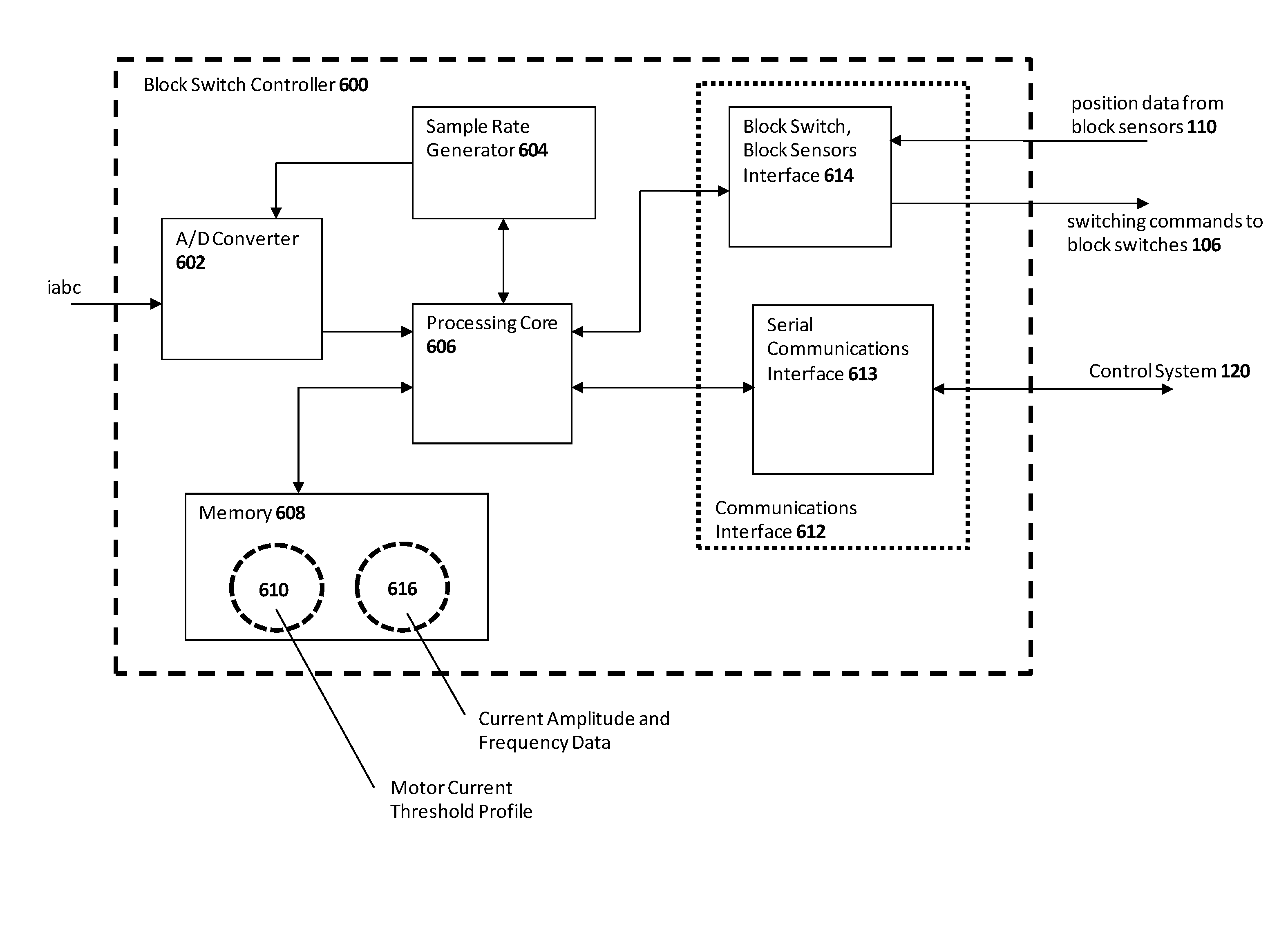
A block switch controller for a linear motor is disclosed, the block switch controller having a motor current threshold profile controlling the switching of a plurality of block switches in a linear motor. Also, a block switch controller for a linear motor comprising a closed loop vector current controller that incorporates a delay state having a feedback gain is disclosed. Additionally, a method of switching a plurality of block switches that minimizes switching transients is provided. Finally, an article of manufacture containing computer code implementing a modeling and simulation program for modeling a linear motor system is provided.

Description

RELATED APPLICATIONS[0001]This application claims priority from U.S. Provisional Application 60 / 917,874 filed May 14, 2007.BACKGROUND OF THE INVENTION[0002]1. Field of Invention[0003]The present invention relates generally to the field of linear motors. More specifically, the present invention is related to a block switch controller for a linear motor that minimizes block switching transients.[0004]2. Discussion of Prior Art[0005]There are many types of linear motor systems including synchronous linear motors, switched reluctance linear motors, permanent magnet linear motors, and linear induction motors (LIM). In each case, the linear motor can be visualized as a rotary motor that has been sliced axially and “unwrapped”. A set of stator coils are energized and a force is generated that propels the moving shuttle across the stator windings but in a linear path rather than in a circular path. FIG. 1 shows a block diagram of a typical linear induction motor system 100 with a series of ...

Claims


Application Information

Patent Timeline
Patent Type & Authority Patents(United States)
IPC IPC(8): H02P25/06
CPCH02P25/06H02P6/006H02P25/062
Inventor SEPE, JR., RAYMOND B.
Owner ELECTRO STANDARDS LAB
Learn More