Electronic device with a distortion correction circuit for a power amplifier, and associated methods

a technology of distortion correction and power amplifier, applied in the field of radio frequency (rf) communication, can solve problems such as signal clipping, undesired intermodulation distortion, and out of band emissions, and achieve the effect of correcting distortion

Active Publication Date: 2011-06-28
HARRIS GLOBAL COMM INC
View PDF14 Cites 14 Cited by
  • Summary
  • Abstract
  • Description
  • Claims
  • Application Information

AI Technical Summary

Benefits of technology

[0010]The first and second logarithmic converters may advantageously correct non-linearity in the amplitude of the output signal from the power amplifier without being dependent on the envelope of the output signal. The first and second logarithmic converters may be matched over an operating temperature range associated with the electronic device.
[0012]By varying the offset to the error integrator, a variable ratio may be achieved between an instant amplitude of the output signal from the power amplifier and that of the reference signal from the signal source. This may advantageously correct non-linearity in the amplitude of the output signal from the power amplifier by removing the feedback gain dependence on the envelope of the output signal from the power amplifier. Further, a consistently high feedback gain may be maintained regardless of a value of the signal envelope and precise automatic transmit gain control (TGC) is simultaneously achieved. Since the power amplifier is allowed to operate in a more non-linear mode, it is more efficient, particularly in terms of power consumption and heat generation.

Problems solved by technology

A power amplifier in an RF transmitter operating at high power levels has non-linear amplifier characteristics that can produce undesired intermodulation distortion due to interaction between the signals being amplified.
This is called compression and will result in the signal being clipped.
This can and often does cause out of band emissions in addition to distorting the amplified signal.
This makes it difficult to maintain a consistently strong feedback.
As waveforms move to higher peak-to-average ratios with higher symbol rates, the envelope gain dependence often results in insufficient distortion correction.

Method used


Image

  • Electronic device with a distortion correction circuit for a power amplifier, and associated methods
  • Electronic device with a distortion correction circuit for a power amplifier, and associated methods
  • Electronic device with a distortion correction circuit for a power amplifier, and associated methods

Examples


Embodiment Construction

[0025]The present invention will now be described more fully hereinafter with reference to the accompanying drawings, in which preferred embodiments of the invention are shown. This invention may, however, be embodied in many different forms and should not be construed as limited to the embodiments set forth herein. Rather, these embodiments are provided so that this disclosure will be thorough and complete, and will fully convey the scope of the invention to those skilled in the art. Like numbers refer to like elements throughout.

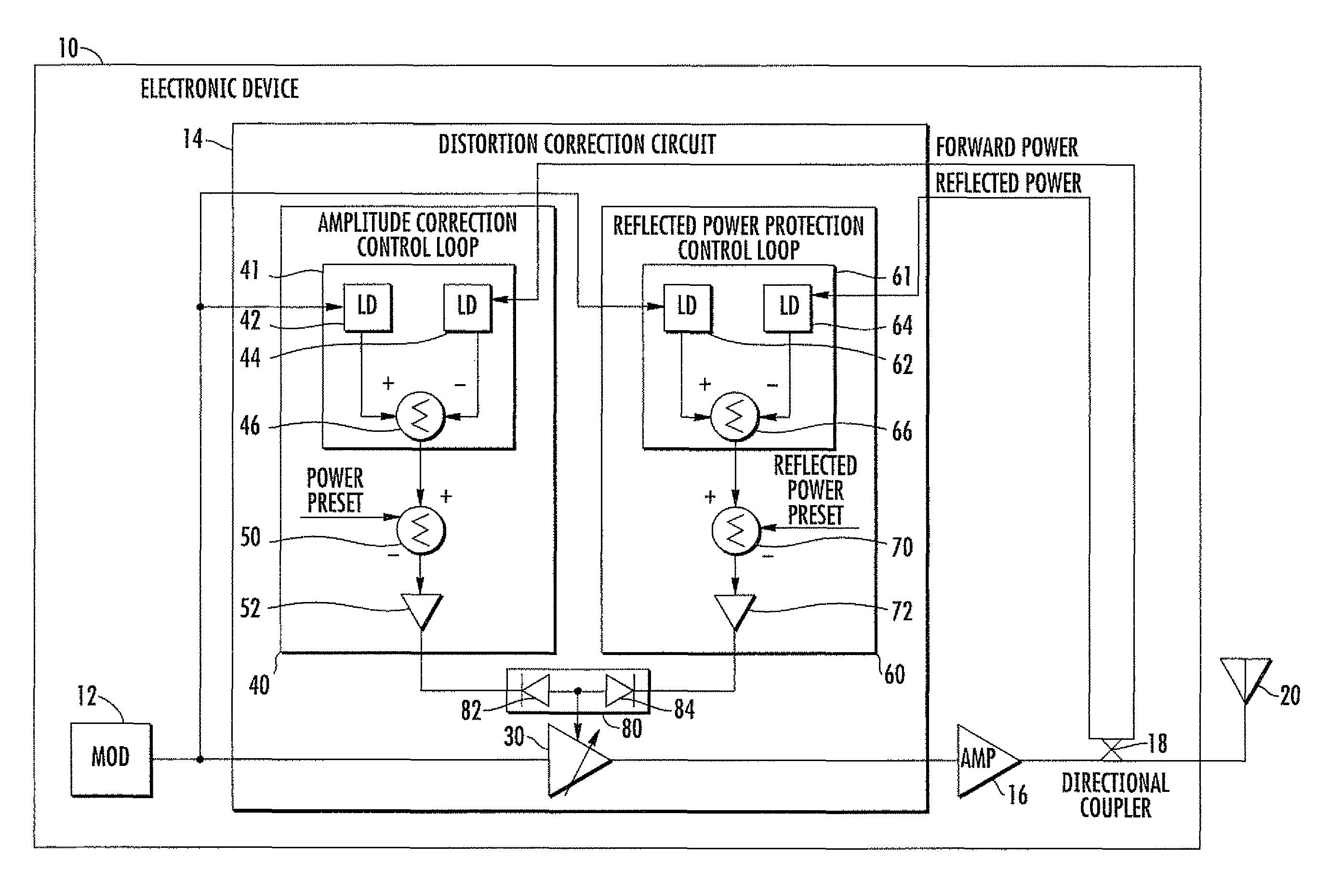
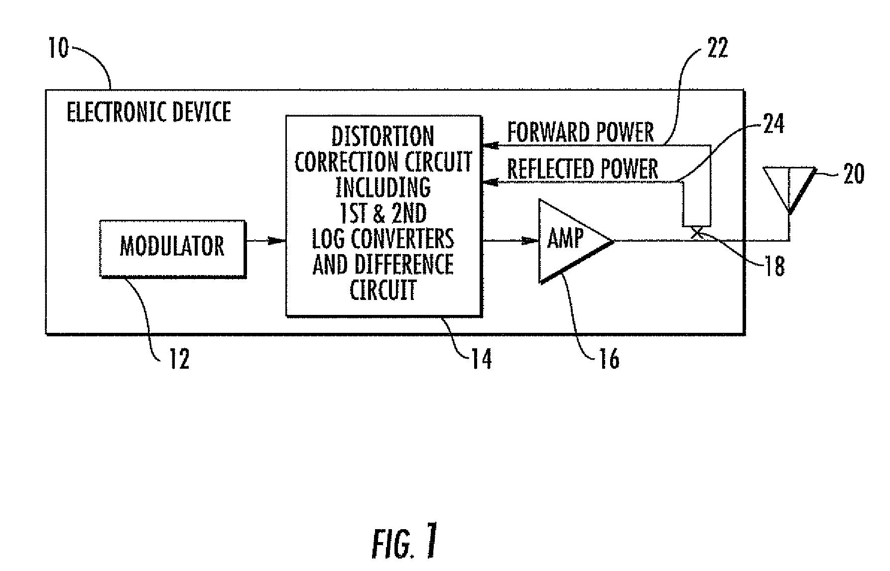
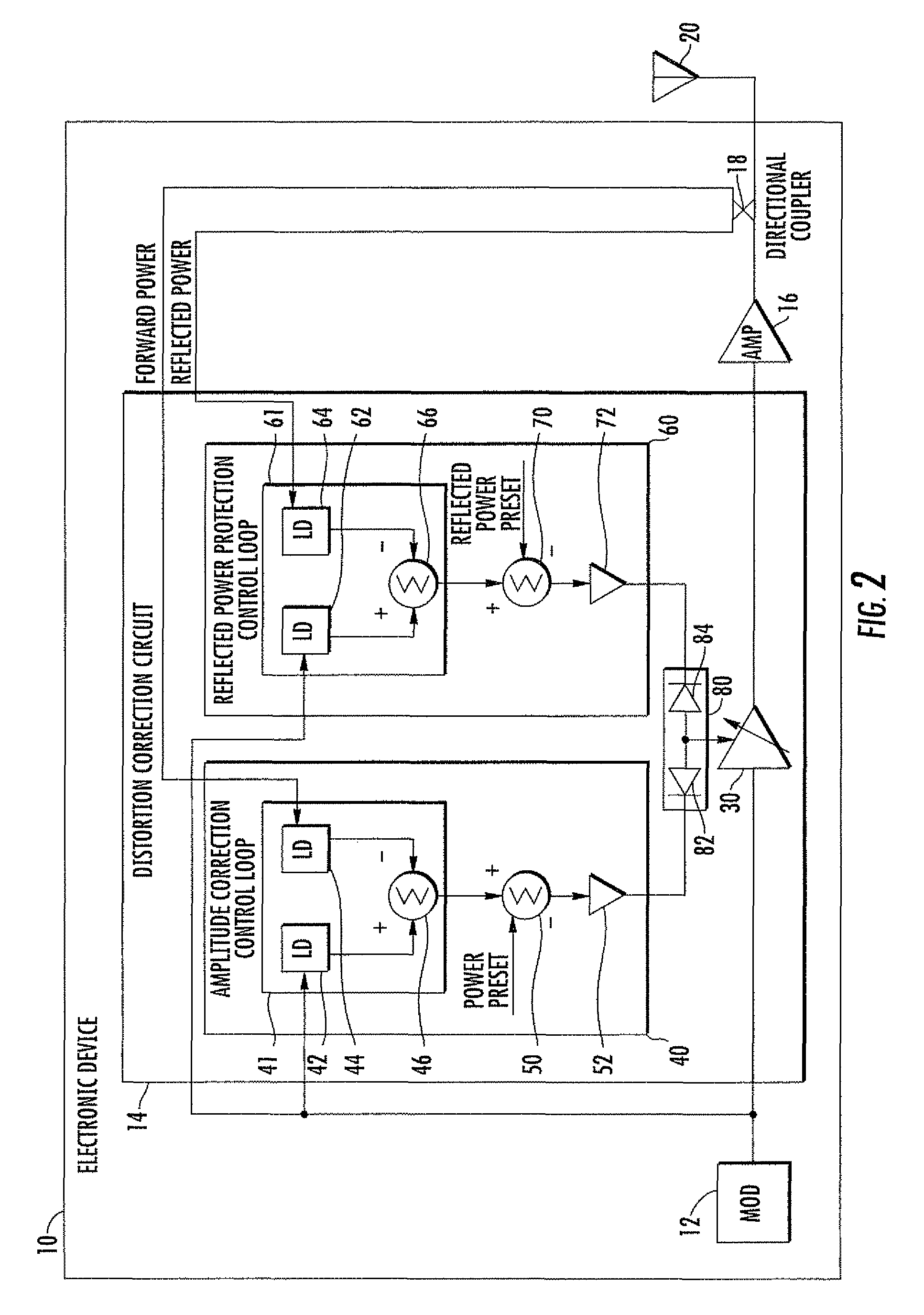
[0026]Referring initially to FIG. 1, the illustrated electronic device 10 includes an RF modulator 12 coupled to an input of a distortion correction circuit 14, and a power amplifier 16 is coupled to an output of the distortion correction circuit. A directional coupler 18 is downstream to the power amplifier 16, and an antenna 20 is downstream to the coupler. The electronic device 10 may be configured as an RF transmitter, for example. The directional coup...


PUM


Abstract

An electronic device includes a radio frequency (RF) modulator, a power amplifier, and a distortion correction circuit coupled between the RF modulator and the power amplifier. The distortion correction circuit includes a variable gain amplifier coupled between the RF modulator and the power amplifier, and an amplitude correction control loop. The amplitude correction control loop includes a first logarithmic converter having an input coupled to the RF modulator, a second logarithmic converter having an input coupled to an output of the power amplifier, and a difference circuit coupled to outputs of the first and second logarithmic converters for controlling the gain of the variable gain amplifier for correcting distortion in an output signal from the power amplifier.

Description

FIELD OF THE INVENTION[0001]The present invention relates to the field of radio frequency (RF) communications, and more particularly, to correcting distortion in an output signal from a power amplifier of an RF transmitter.BACKGROUND OF THE INVENTION[0002]A power amplifier in an RF transmitter operating at high power levels has non-linear amplifier characteristics that can produce undesired intermodulation distortion due to interaction between the signals being amplified. Often referred to as a non-linear device, a power amplifier has linear regions and non-linear regions. To avoid signal distortion, a power amplifier needs to be used in the linear regions.[0003]In the non-linear regions, signals from the power amplifier will be subject to amplitude to amplitude modulation. This is caused by the fact that as the power amplifier is operated in the non-linear regions, the ratios of input to output power are not constant. As the input signal amplitude increases, there will be a disprop...

Claims


Application Information

Patent Timeline
Patent Type & Authority Patents(United States)
IPC IPC(8): H04B1/04
CPCH03F1/345H03F3/46H03F3/24
Inventor PEI, ALEXANDER X.
Owner HARRIS GLOBAL COMM INC
Why Eureka
Try Eureka