Method and apparatus for detecting object orientation and position

a technology of applied in the field of implanted devices and methods for detecting object orientation and position, can solve the problems of conventional numerical methods, set design limitations, and inability to investigate the local minimum points associated, etc., and achieve the effect of reducing noise, accurate, fast and continuous

a technology of applied in the field of implanted devices and methods for detecting object orientation and position, can solve the problems of conventional numerical methods, set design limitations, and inability to investigate the local minimum points associated, etc., and achieve the effect of reducing noise, accurate, fast and continuous

US7970477B2Inactive Publication Date: 2011-06-28ALFRED E MANN INST FOR BIOMEDICAL ENG AT THE UNIV OF SOUTHERN CALIFORNIA

Image

  • Method and apparatus for detecting object orientation and position
  • Method and apparatus for detecting object orientation and position
  • Method and apparatus for detecting object orientation and position

Examples


Embodiment Construction

[0027]The detailed description set forth below is intended as a description of exemplary embodiments of the present invention and is not intended to represent the only embodiments in which the present invention can be practiced. The term “exemplary” used throughout this description means “serving as an example, instance, or illustration,” and should not necessarily be construed as preferred or advantageous over other embodiments. The detailed description includes specific details for the purpose of providing a thorough understanding of the present invention. However, it will be apparent to those skilled in the art that the present invention may be practiced without these specific details. In some instances, well-known structures and devices are shown in block diagram form in order to avoid obscuring the concepts of the present invention.

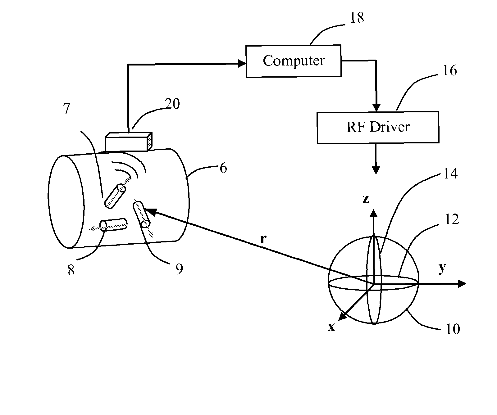
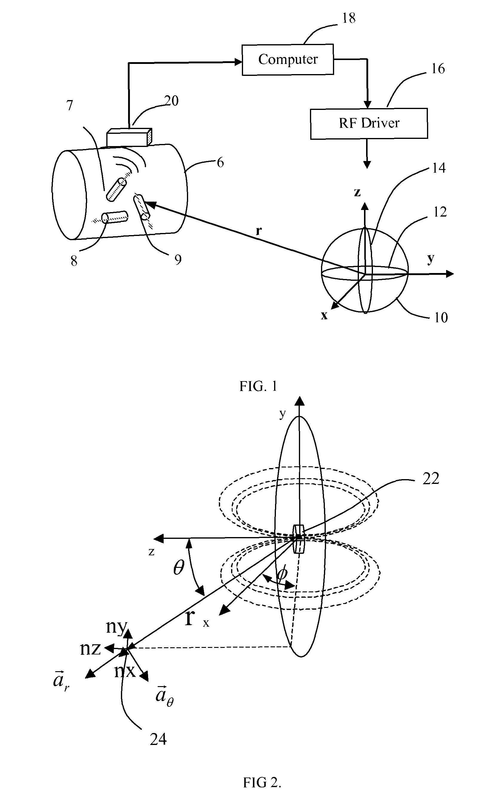
[0028]In FIG. 1, a functional diagram of the distributed sensing system is illustrated. A multi-dimensional AC magnetic source 20 (that includes sev...


PUM


Abstract

A signal transmitting and receiving system to track the position and orientation of limb segments in order to provide feedback information for the control of the limb movement. The user will generally be seated in a wheelchair that provides a structure upon which orthogonal and / or non-orthogonally oriented coils can be mounted and energized selectively so as to create variously oriented magnetic fields. Multiple wireless sensors injected into the limb detect the local field strength and send information telemetrically to a central controller. The controller extracts information about the position and orientation of each limb segment by combining signals from various sensors according to calibration information and optimal filtering methods for extracting information from multiple nonlinear sensors in mechanically constrained systems.

Description

CROSS REFERENCE TO RELATED APPLICATIONS[0001]This United States patent application is a continuation of U.S. application Ser. No. 11 / 457,101, filed Jul. 12, 2006, now abandoned entitled “Method and Apparatus for Detecting Object Orientation and Position,” which is related to and claims the benefit of the filing date of U.S. Provisional Patent Application Ser. No. 60 / 698,313, filed Jul. 12, 2005, entitled “Method and Apparatus for Detecting Object Orientation and Position,” the contents of both of which are incorporated herein by reference. This United States patent application is also related to co-pending U.S. patent application Ser. No. 11 / 457,004, also filed on Jul. 12, 2006, entitled “Probe for Identifying Injection Site for Deep Brain Neural Prostheses,” inventor Gerald E. Loeb, the contents of which are also incorporated herein by reference.BACKGROUND OF THE INVENTION[0002]1. Field of the Invention[0003]The present invention relates generally to implanted devices and methods f...

Claims


Application Information

Patent Timeline
28 Jun 2011
Publication
US7970477B2
IPC
A61N1/05
CPC
A61B5/06; A61B5/1116; A61B5/1121; A61N1/36003; A61B2562/162; A61B5/6861; A61B2560/0219; A61B2562/0223
Inventors
LOEB, GERALD E.; TAN, WEI