Information processing apparatus and information processing method
a technology of information processing apparatus and information processing method, which is applied in the direction of image enhancement, navigation instruments, instruments, etc., can solve the problem that the orientation measurement value of the orientation sensor cannot be used intact, and achieve the effect of easy and precise calibration of the orientation sensor
- Summary
- Abstract
- Description
- Claims
- Application Information
AI Technical Summary
Benefits of technology
Problems solved by technology
Method used
Image

Examples
first embodiment
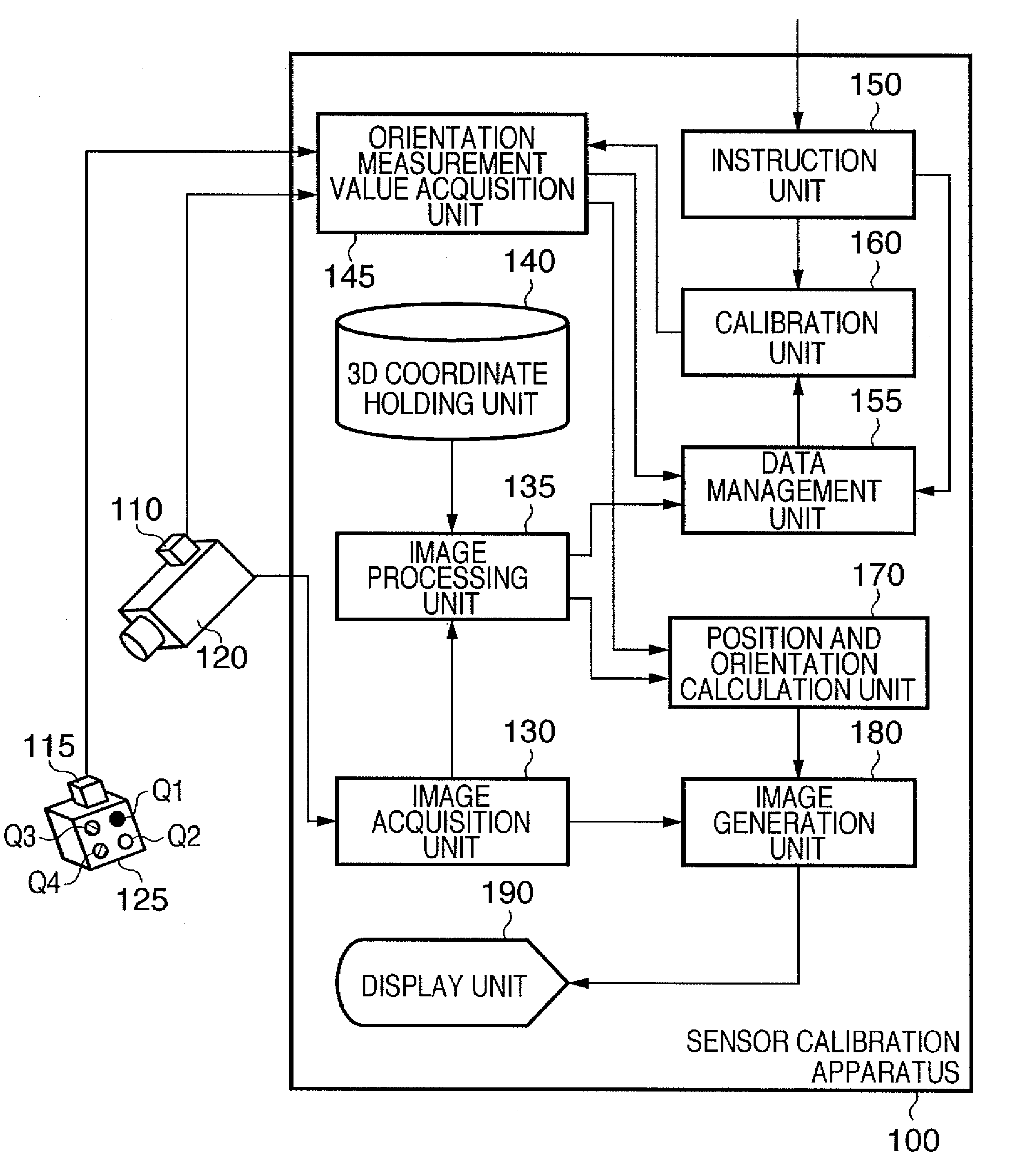
[0055]An information processing apparatus according to this embodiment calibrates an orientation sensor mounted on an image capturing apparatus such as a video camera or the like (orientation sensor for an image capturing apparatus) and that mounted on a physical object (orientation sensor for a physical object) at the same time. Therefore, the information processing apparatus according to this embodiment will be referred to as a sensor calibration apparatus hereinafter. This sensor calibration apparatus and a sensor calibration method executed by this sensor calibration apparatus will be described below.
[0056]FIG. 1 is a block diagram showing the functional arrangement of a system having a sensor calibration apparatus according to this embodiment. As shown in FIG. 1, orientation sensors 110 and 115 to be calibrated, and an image capturing apparatus 120 represented by a video camera, which can capture a movie, are connected to a sensor calibration apparatus 100.
[0057]The sensor cali...
second embodiment
[0144]In the first embodiment, the orientation sensor 110 is mounted on the image capturing apparatus 120. However, in consideration of only the object of measuring the allocation information of the orientation sensor 115 mounted on the physical object 125, the orientation sensor 110 need not to always be mounted on the image capturing apparatus 120. This embodiment will explain a system when no orientation sensor is mounted on the image capturing apparatus 120.
[0145]FIG. 5 is a block diagram showing the functional arrangement of a system having a sensor calibration apparatus according to this embodiment. The same reference numerals in FIG. 5 denote the same components shown in FIG. 1, and a repetitive description thereof will be avoided. The arrangement shown in FIG. 5 is different from that shown in FIG. 1 in the following three points.[0146]No orientation sensor is mounted on the image capturing apparatus 120.[0147]The orientation of the image capturing apparatus 120 is fixed by ...
third embodiment
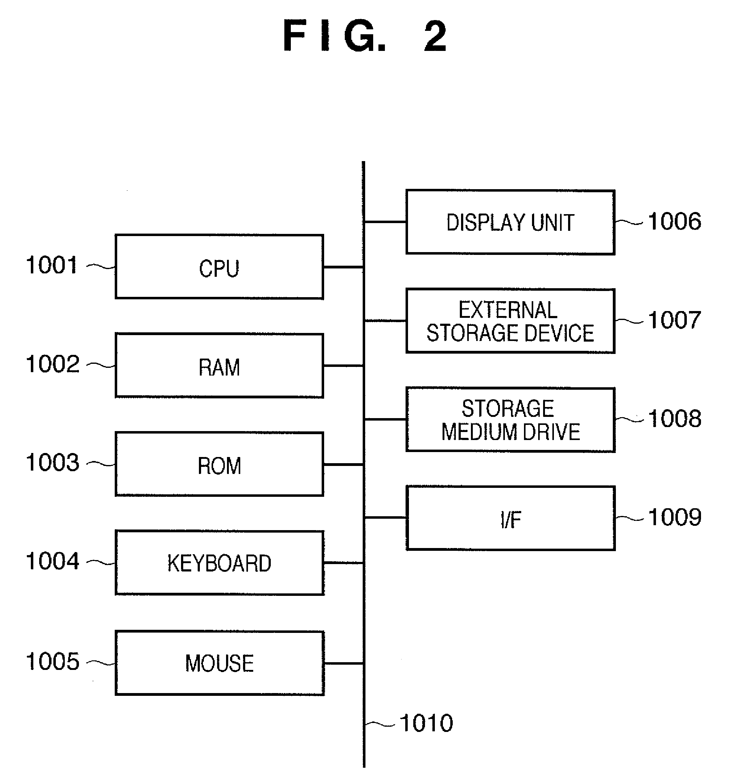
[0173]In the above description, all the units which configure the sensor calibration apparatus 100 or 500 shown in FIG. 1 or 5 are implemented by hardware components. However, some or all of units except for the components which hold data may be implemented by software (computer program). In this case, such software is loaded onto a memory of a computer such as a PC (personal computer) or the like, and a CPU of this computer executes that software. As a result, the computer can execute the same processing as the sensor calibration apparatus 100 or 500 shown in FIG. 1 or 5.
[0174]FIG. 2 is a block diagram showing the hardware arrangement of a computer which can be applied to the sensor calibration apparatuses 100 and 500.
[0175]A CPU 1001 controls the overall computer using programs and data stored in a RAM 1002 and ROM 1003, and executes the aforementioned processes to be implemented by the sensor calibration apparatus 100 or 500 to which this computer is applied.
[0176]The RAM 1002 ha...
PUM
 Abstract
Description
Claims
Application Information
 - R&D
- Intellectual Property
- Life Sciences
- Materials
- Tech Scout
- Unparalleled Data Quality
- Higher Quality Content
- 60% Fewer Hallucinations
Browse by: Latest US Patents, China's latest patents, Technical Efficacy Thesaurus, Application Domain, Technology Topic, Popular Technical Reports.
© 2025 PatSnap. All rights reserved.Legal|Privacy policy|Modern Slavery Act Transparency Statement|Sitemap|About US| Contact US: help@patsnap.com