POS device

a pos device and pos technology, applied in the direction of electrical apparatus construction details, electrical apparatus casings/cabinets/drawers, instruments, etc., can solve the problems of insufficient number of clerks, incompatibility with store environment, and cost of two pos devices in a store, so as to minimize installation space and low cost

Active Publication Date: 2011-06-28
NEC PLATFORMS LTD
View PDF17 Cites 28 Cited by
  • Summary
  • Abstract
  • Description
  • Claims
  • Application Information

AI Technical Summary

Benefits of technology

Therefore, this invention has been made in view of the above problems of the prior art and has an object to provide a POS device that is simple in structure and excellent in operability with high switching speed by sharing the single POS device.
In this manner, according to this invention, a single device can be used as both a POS device adapted to be operated by a clerk (clerk-service POS) and as a self-type POS device adapted to be operated by a shopping customer himself or herself (self-service POS) so that the single POS device can have two functions for clerk service and self-service. This makes it possible to achieve a low cost and minimize the installation space.

Problems solved by technology

In a recent retail store environment, there have been cases where the number of clerks is insufficient due to compression of labor cost and a decrease in population and where the goods cannot be sufficiently displayed for reasons of small area of a store.
However, it is costly for a store to purchase two POS devices, i.e. the clerk POS device and the self-service POS device.
Further, this requires the installation space to be twice or more and thus does not match the store environment.
Moreover, in a time zone when there is no clerk in the store, the clerk POS device is unusable, i.e. being an unused installation, and thus is wasted.
However, since this conventional system is configured such that a scanner and an LCD are movable independently of each other, the system configuration is complicated.
Further, since two actions are required for switching between the self-service POS device and the clerk POS device, the speed for the switching is slow.
Further, a receipt printer is required for printing receipts, but is not provided in this conventional system.
Moreover, POP advertisements or the like are normally posted in stores, but, according to this prior art, since the size of the system is large and driving portions are located away from each other, it is not possible to place POP advertisements or the like therearound.

Method used


Image

  • POS device
  • POS device
  • POS device

Examples


example

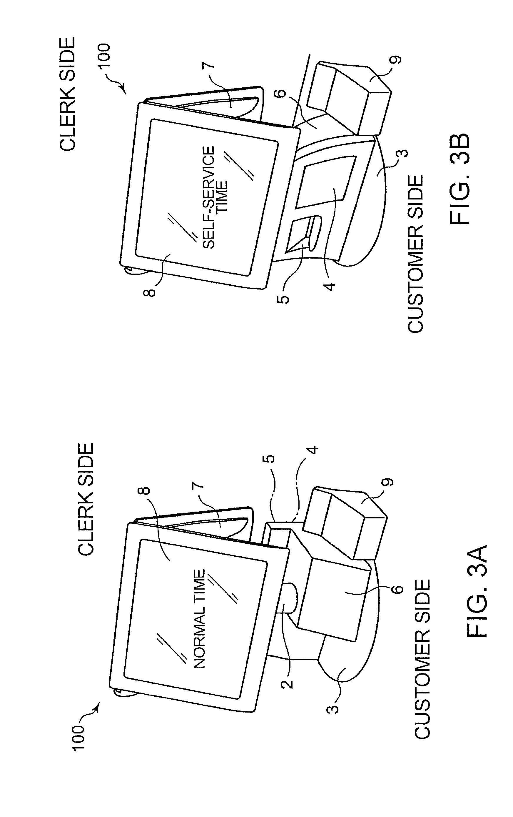
Now, an example of this invention will be described with reference to FIGS. 6 and 7.

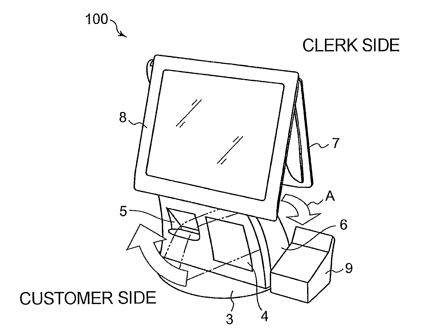
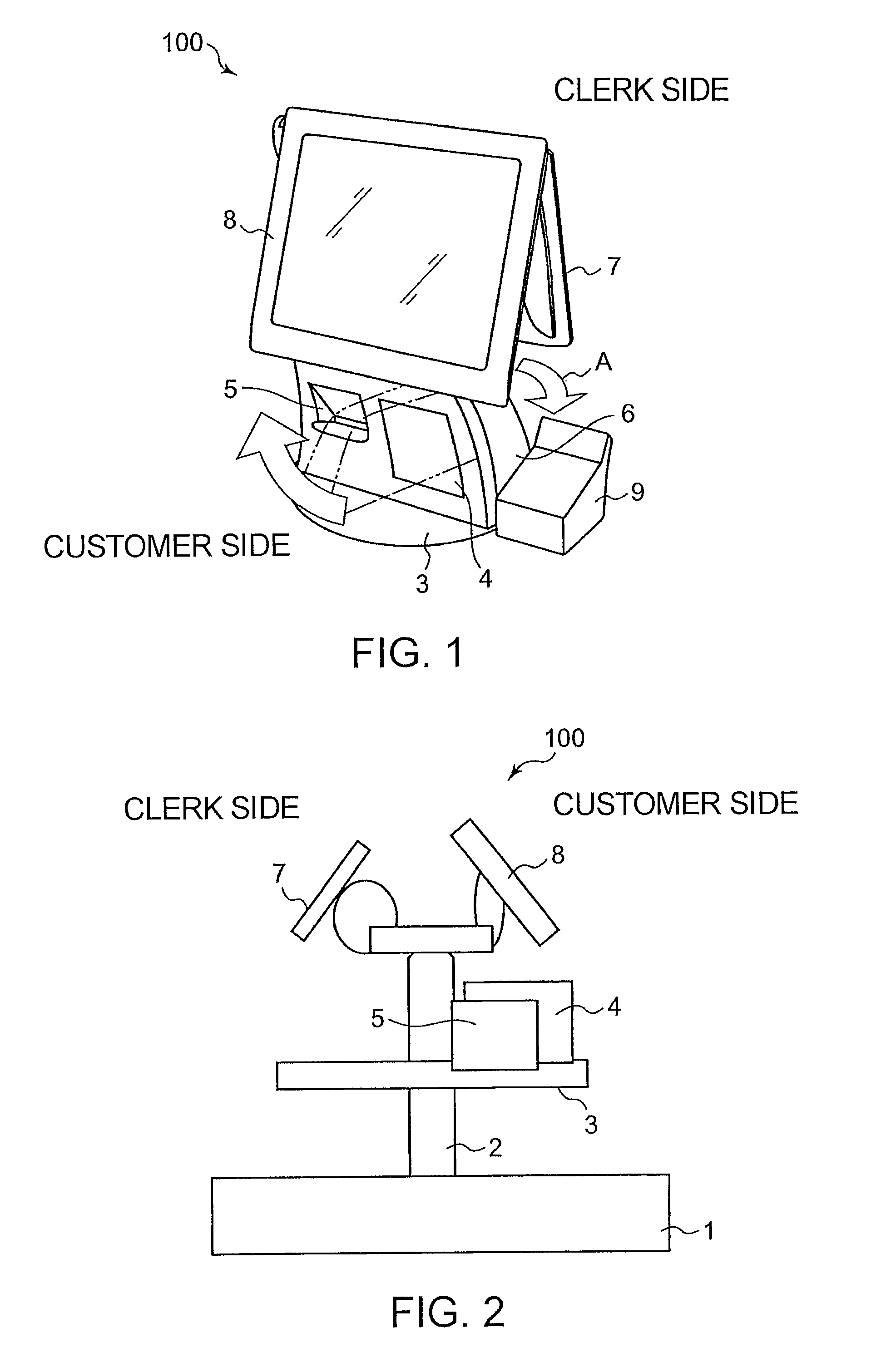
FIG. 6 is a diagram illustrating a specific configuration of a POS device 100 in clerk-service time. FIG. 7 is a diagram illustrating a specific configuration of the POS device 100 in customer-service time. Herein, the same reference numerals are assigned to the same constituent portions as those in FIGS. 1 to 4.

The POS device 100 is installed on a base 61 disposed on a desk 1. The base 61 is provided with a cash drawer 62 for keeping money for change and received money. The cash drawer 62 is connected to the POS device 100. The POS device 100 is provided with a barcode hand scanner 63. The barcode hand scanner 63 is a handheld scanner for assisting a stationary barcode scanner 4. The barcode hand scanner 63 is not used in self-service time. This is because, normally, customers unfamiliar with handheld scanner operation do not use the barcode hand scanner 63. The barcode hand scanner 63 is secondaril...


PUM


Abstract

A POS device includes a rotation shaft vertically fixed, a rotary plate provided so as to be rotatable about the rotation shaft, a rotating portion placed on the rotary plate and having at least a barcode scanner and a receipt printer, and a display device for clerk and a display device for customer both provided at the top end of the rotation shaft.

Description

This application is based upon and claims the benefit of priority from Japanese Patent Application No. 2008-23530, filed on Feb. 4, 2008, the disclosure of which is incorporated herein in its entirety by reference.TECHNICAL FIELDThis invention relates to a POS device that automatically reads and registers information about purchased items.BACKGROUND ARTIn a recent retail store environment, there have been cases where the number of clerks is insufficient due to compression of labor cost and a decrease in population and where the goods cannot be sufficiently displayed for reasons of small area of a store. For reducing the number of clerks or shortening waiting time at the cashier counter, introduction of a self-service POS device in addition to a clerk POS device has been progressing. However, it is costly for a store to purchase two POS devices, i.e. the clerk POS device and the self-service POS device. Further, this requires the installation space to be twice or more and thus does n...

Claims


Application Information

Patent Timeline
Patent Type & Authority Patents(United States)
IPC IPC(8): G06Q20/00G07G1/00G07G1/01G07G1/12
CPCG06Q20/204G07G1/0018G06Q20/208
Inventor TOKOROTANI, MITSUHIRO
Owner NEC PLATFORMS LTD
Why Eureka
Try Eureka