Heat exchanger with drain grooves

a heat exchanger and drain groove technology, applied in the field of heat exchangers, can solve the problems of affecting the performance of the evaporator, affecting the efficiency of the evaporator, and a large amount of condensation water collected, so as to improve the efficiency of heat exchange and facilitate the making. , the effect of preventing impairment of performan

Inactive Publication Date: 2011-07-05
MAHLE INT GMBH
View PDF19 Cites 15 Cited by
  • Summary
  • Abstract
  • Description
  • Claims
  • Application Information

AI Technical Summary

Benefits of technology

[0033]With the heat exchanger according to par. 1), the lower tank has drain grooves each extending from the forwardly or rearwardly outer end of each of the tube insertion holes for discharging condensation water to below the lower tank therethrough, so that the condensation water flowing down onto the lower tank flows through the drain grooves and is discharged to below the lower tank. Accordingly, the upper surface of the lower tank can be drained of condensation water with an improved efficiency, preventing a large amount of condensation water from collecting on the lower tank and from freezing, whereby impairment of the performance can be precluded when the heat exchanger is used as an evaporator. Stated more specifically, the water condensate produced over the surfaces of the fins and heat exchange tubes generally flows down along the forwardly or rearwardly outer ends of the tubes. When the drain grooves formed extend from the forwardly or rearwardly outer ends of the respective tube insertion holes, the water flowing down along the forwardly or rearwardly outer ends of the tubes enters directly into the drain grooves, consequently flows through the drain grooves and is smoothly discharged to below the lower tank to give the lower tank improved drainage efficiency.
[0046]With the heat exchanger according to par. 17), heat exchange efficiency can be improved, and the increase in air passage resistance suppressed, with a good balance maintained therebetween.

Problems solved by technology

Consequently, a relatively great amount of condensation water collects on the top surface of the lower tank and is liable to freeze, entailing the likelihood of impairing the performance of the evaporator.

Method used


Image

  • Heat exchanger with drain grooves
  • Heat exchanger with drain grooves
  • Heat exchanger with drain grooves

Examples


Embodiment Construction

[0056]An embodiments of the present invention will be described below with reference to the drawings. The embodiment is a heat exchanger of the invention for use as an evaporator in motor vehicle air conditioners wherein a chlorofluorocarbon refrigerant is used.

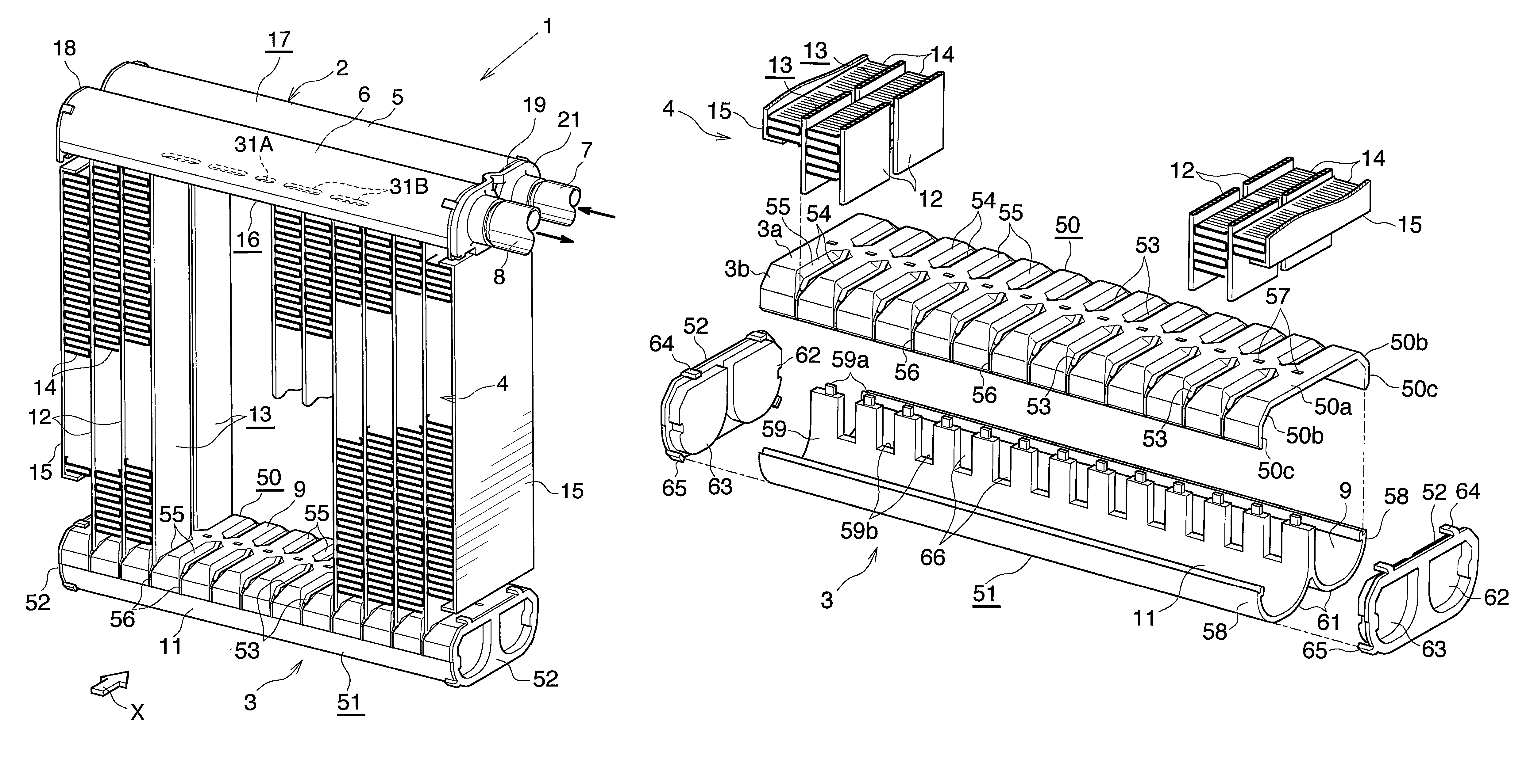
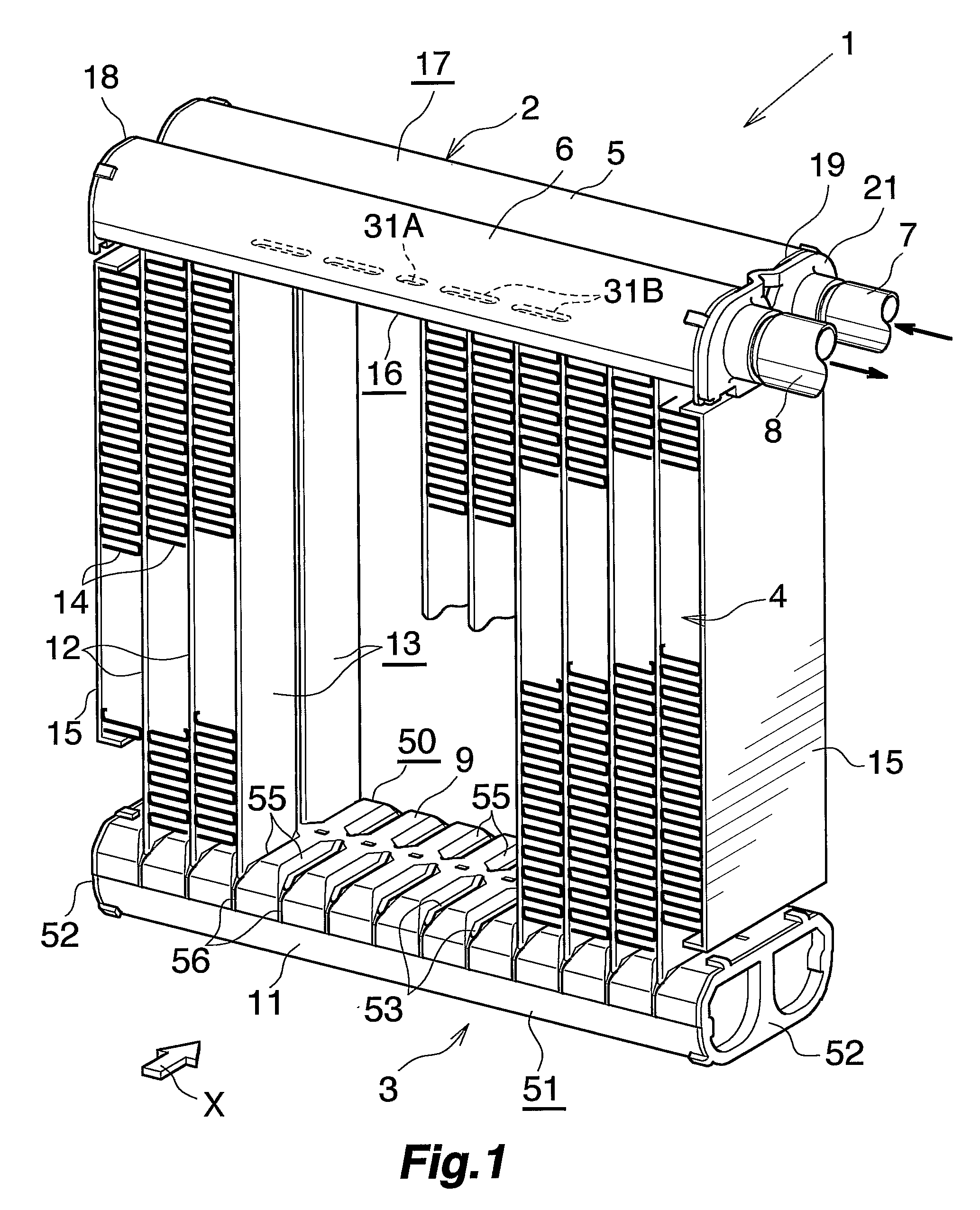
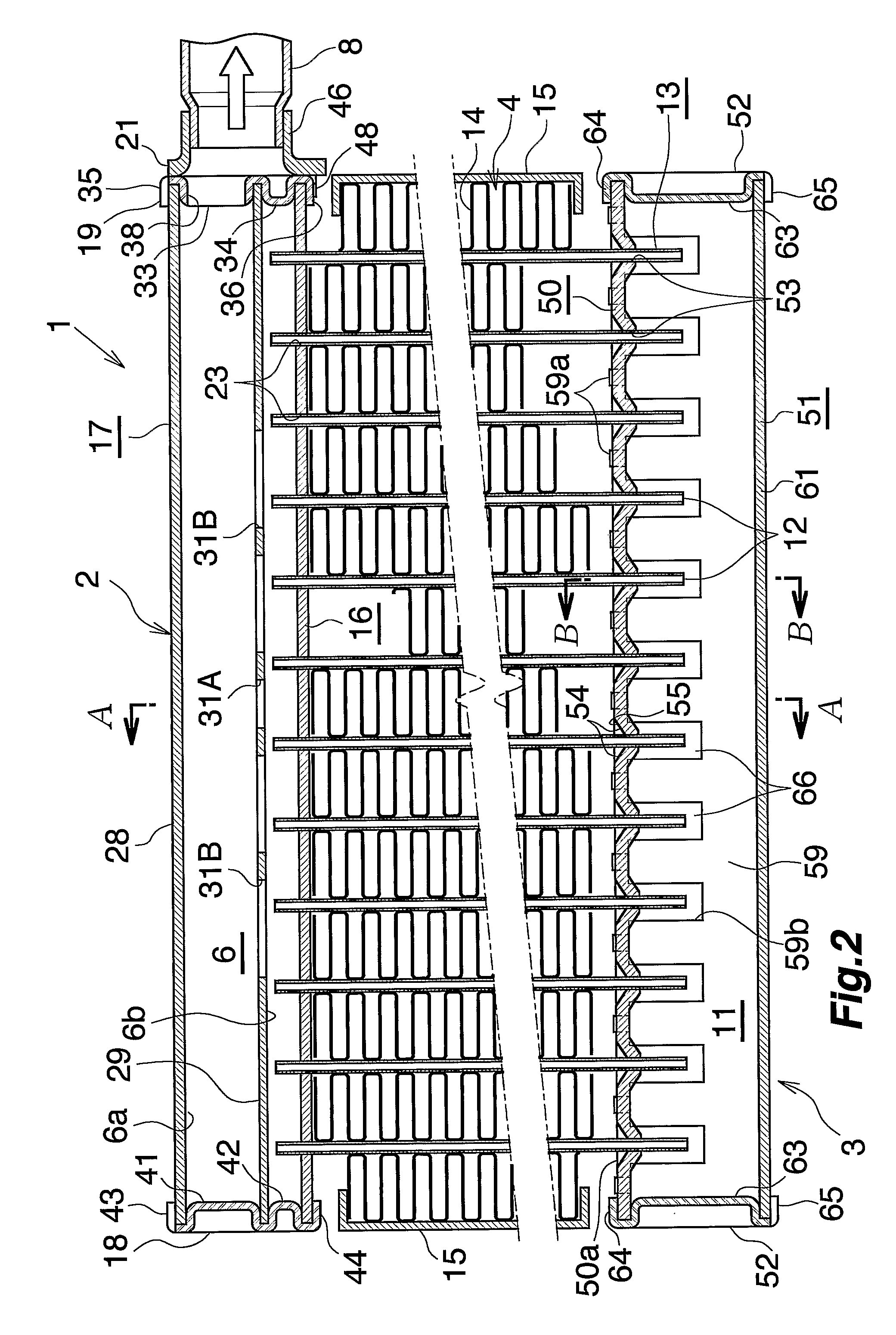
[0057]FIGS. 1 and 2 show the overall construction of a motor vehicle air conditioner evaporator to which the heat exchanger of the invention is applied, FIGS. 3 to 8 show the constructions of main parts, and FIG. 9 shows how the refrigerant flows through the evaporator.

[0058]FIG. 1 and 2 show an evaporator 1 for use in motor vehicle air conditioners wherein a chlorofluorocarbon refrigerant is used. The evaporator 1 comprises a refrigerant inlet-outlet tank 2 of aluminum and a refrigerant turn tank 3 of aluminum (lower tank) which are arranged as vertically spaced apart, and a heat exchange core 4 provided between the two tanks 2, 3.

[0059]The refrigerant inlet-outlet tank 2 comprises a refrigerant inlet header 5 positioned on ...


PUM


Abstract

A heat exchanger for use as an evaporator includes a heat exchange core having a plurality of heat exchange tubes arranged in a left-right direction at a spacing, and a refrigerant turn tank as a lower tank disposed toward a lower end of the heat exchange core. The heat exchange tubes are inserted through respective tube insertion holes formed in the turn tank and joined to the tank. The turn tank has drain grooves each extending from a forwardly or rearwardly outer end of each of the tube insertion holes for discharging condensation water to below the turn tank therethrough. Each of the drain grooves has a bottom extending gradually downward as the bottom extends away from the tube insertion hole. the exchanger is used as the evaporator, the top surface of the turn tank can be drained of water with an improved efficiency.

Description

CROSS REFERENCE TO RELATED APPLICATION[0001]This application is an application filed under 35 U.S.C. §111(a) claiming the benefit pursuant to 35 U.S.C. §119(e)(1) of the filing dates of Provisional Applications No. 60 / 585,835 and No. 60 / 688,353 filed Jul. 8, 2004 and Jun. 8, 2005, respectively, pursuant to 35 U.S.C. §111(b).TECHNICAL FIELD[0002]The present invention relates to heat exchangers suitable to use, for example, as evaporators in motor vehicle air conditioners which are refrigeration cycles for use in motor vehicles.[0003]The downstream side (the direction indicated by the arrow X in FIG. 1, the right-hand side of FIG. 3) of the flow of air to be passed through air passage clearances between respective adjacent pairs of heat exchange tubes of the heat exchanger will be referred to herein and in the appended claims as “front,” and the opposite side as “rear.” Further the upper, lower, left and right sides of the heat exchanger as it is seen from behind toward the front (the...

Claims


Application Information

Patent Timeline
Patent Type & Authority Patents(United States)
IPC IPC(8): F28F9/02F28D7/06F25D21/14
CPCB60H1/00328F25B39/02F28D1/05391F28F9/0224F28F9/0278F28F17/005F25B2309/061F28F2220/00F28F2265/06
Inventor HIGASHIYAMA, NAOHISAWATANABE, SUMITAKAYAMAUCHI, SHINOBU
Owner MAHLE INT GMBH
Why Eureka
Try Eureka