Dual mini well surface control system

a control system and mini well technology, applied in the direction of drilling casings, drilling pipes, borehole/well accessories, etc., can solve the problems of high pressures that can reach several thousands of pounds per square inch, and achieve the effect of fast and easy connection and faster rig-up and rig-down tim

Active Publication Date: 2011-07-05
DEVIN INT
View PDF7 Cites 30 Cited by
  • Summary
  • Abstract
  • Description
  • Claims
  • Application Information

AI Technical Summary

Benefits of technology

[0005]An advantage of the present invention is that it provides a single, compact system for controlling pressure in a well and for severing components of a work string. Another advantage of the present invention is that it provides a locking mechanism to keep crossovers securely connected to the system in a derrick of a rig. Still another advantage of the present invention is that it can be quickly and easily connected to any type work string. Yet another advantage of the present invention is that it provides a faster rig-up and rig-down time than conventional blow out preventers.
is that it provides a single, compact system for controlling pressure in a well and for severing components of a work string. Another advantage of the present invention is that it provides a locking mechanism to keep crossovers securely connected to the system in a derrick of a rig. Still another advantage of the present invention is that it can be quickly and easily connected to any type work string. Yet another advantage of the present invention is that it provides a faster rig-up and rig-down time than conventional blow out preventers.

Problems solved by technology

These high pressures may reach several thousands of pounds per square inch.

Method used


Image

  • Dual mini well surface control system
  • Dual mini well surface control system
  • Dual mini well surface control system

Examples


Embodiment Construction

[0012]While the present invention will be described with reference to preferred embodiments, it will be understood by those skilled in the art that various changes may be made and equivalents may be substituted for elements thereof without departing from the scope of the invention. In addition, many modifications may be made to adapt a particular situation or material to the teachings of the invention without departing from the essential scope thereof. Therefore, it is intended that the present invention not be limited to the particular embodiments disclosed as the best mode contemplated for carrying out this invention, but that the invention will include all embodiments (and legal equivalents thereof) falling within the scope of the appended claims.

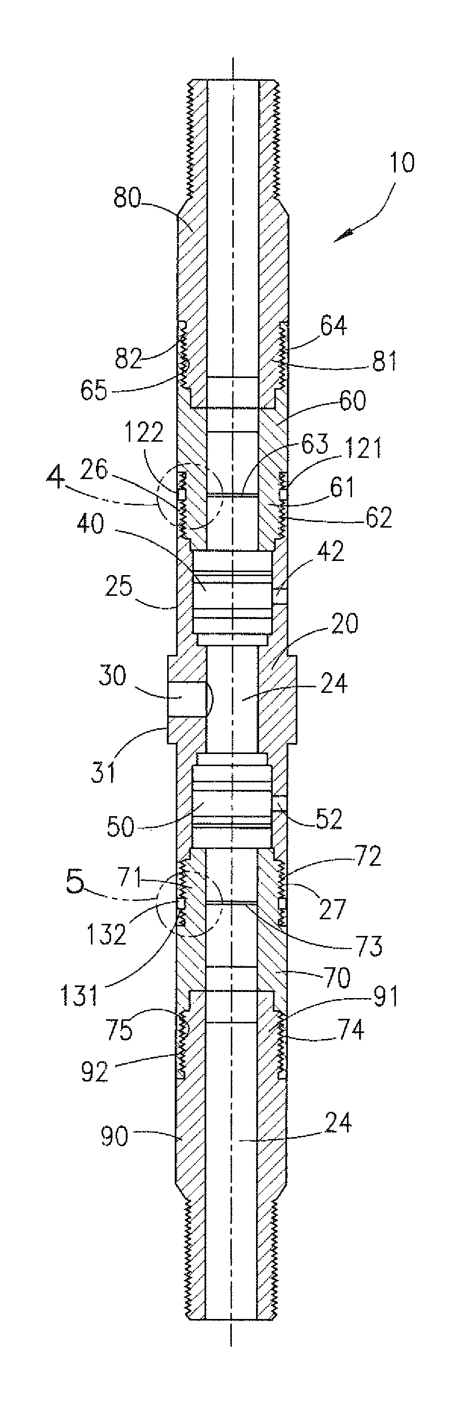
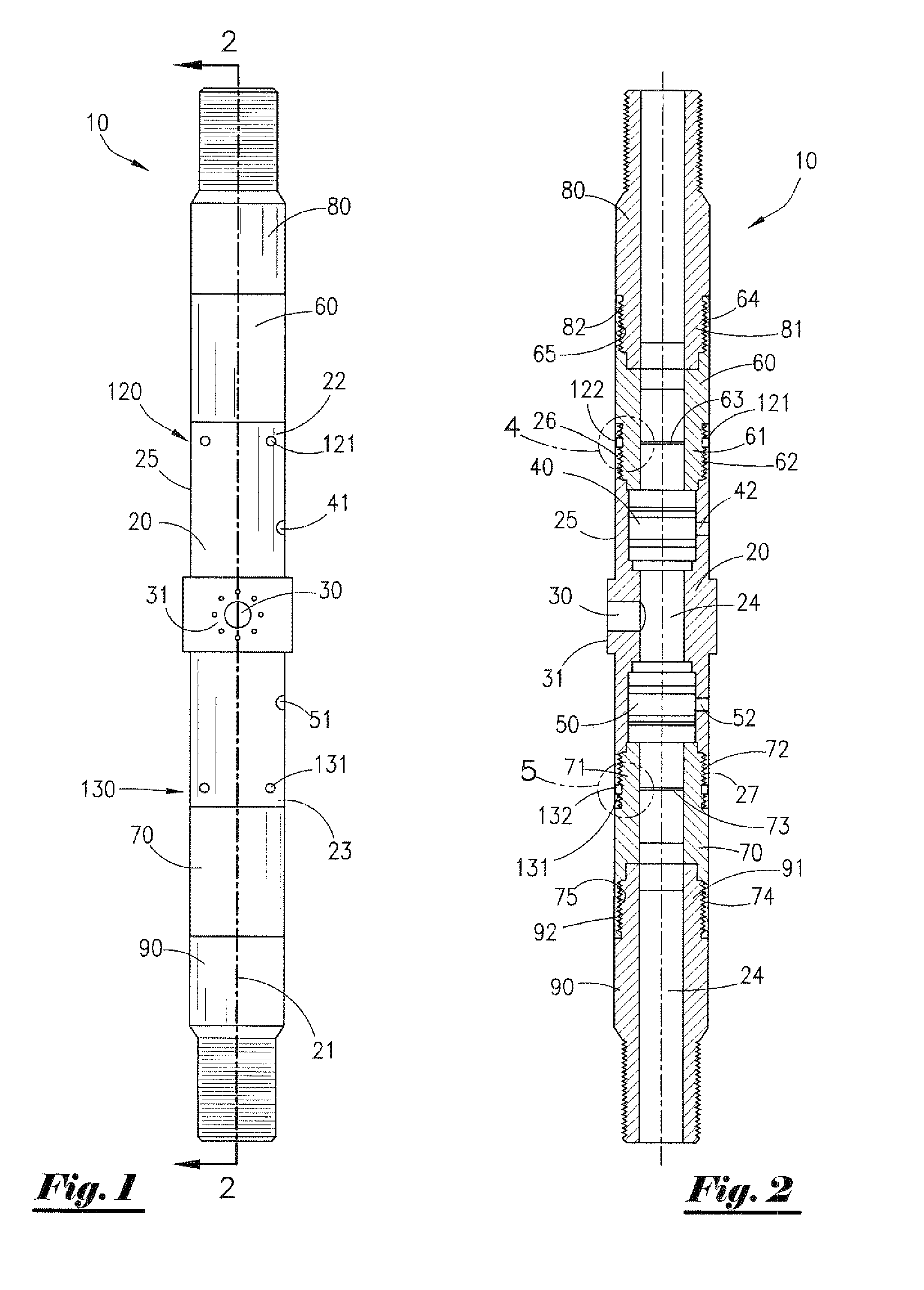
[0013]A preferred embodiment of the present invention is shown in FIGS. 1 and 2. Well surface control system 10 includes a main housing 20, wherein said main housing 20 has a longitudinal axis 21, a first end 22, a second end 23, and an ...


PUM


Abstract

A well surface control system for use with various types of work strings such as, but not limited to, drill strings, coiled tubing, snubbing pipe, electric line, production tubing, and wireline. The system includes a main housing with a main bore extending from one end to the other. The main housing is equipped with a side port which communicates with the main bore between the two ends. The main housing is also equipped with two valves for controlling fluid and / or gas flows through the main bore and for severing a component of a work string running through the main bore. The first valve is positioned between the side port and one end of the main housing and the second valve is positioned between the side port and the other end of the main housing. Attached to each end of the main housing is a saver sub, with means for temporarily locking the saver subs to the main housing to prevent circular and longitudinal movement of the saver subs in relation to the main housing.

Description

FIELD OF THE INVENTION[0001]The subject invention relates generally to an apparatus for controlling a well on a rig or platform.BACKGROUND OF THE INVENTION[0002]In the course of drilling, completing, and producing subterranean reservoirs, operators find it necessary to rig up and run into a well various types of work strings. Examples of work strings include, but are not limited to, drill strings, coiled tubing, snubbing pipe, electric line, production tubing, and wireline.[0003]When working with subterranean reservoirs, operators are always concerned about the high pressure that may exist in such reservoirs. These high pressures may reach several thousands of pounds per square inch. Thus, during any type of operation involving work strings that are run into a well, operators will employ various types of valves at the surface of the well to isolate the crew members working on the well from the high pressure within the reservoir.SUMMARY OF THE INVENTION[0004]The present invention is ...

Claims


Application Information

Patent Timeline
Patent Type & Authority Patents(United States)
IPC IPC(8): E21B34/02E21B29/04
CPCE21B33/068E21B33/072
Inventor DUHON, BRYAN LEEDUCOTE, WAYNE
Owner DEVIN INT
Why Eureka
Try Eureka