Pipe joint, refrigeration device, heat pump hot water supply device, closing valve, water supply piping, method of connecting piping, and in-the field piping method

a technology of pipe joints and water supply pipes, applied in the field of pipe joints, can solve the problems of reducing workability, affecting the workability of pipes, and reducing workability, so as to enhance the workability of pipe joining operation, safe and easy

Inactive Publication Date: 2011-07-05
DAIKIN IND LTD
View PDF34 Cites 7 Cited by
  • Summary
  • Abstract
  • Description
  • Claims
  • Application Information

AI Technical Summary

Benefits of technology

[0005]However, the pipe joint as described above is constructed by the joint body, the nut, and the sleeve, and thus there is a risk that a sleeve, which is a relatively small part, may be lost until a pipe is joined. Furthermore, when a pipe is joined, a sleeve, which is a small part, is assembled to the pipe. This can lower the workability. Furthermore, with respect to the sleeve, the site receiving pressing force and the site biting into the pipe are exposed, and thus when the sleeve is stored as a spare or the sleeve is handled, these sites are liable to scratching. This scratching may adversely affect the sealing performance of the joint portion of the pipe joint.
[0006]An objective of the present invention is to provide a pipe joint that prevents loss of a sleeve and ensures the sealing performance of a joint portion while enhancing the workability at the pipe joining operation, a refrigeration device using the pipe joint, etc., a method for connecting piping, etc.

Problems solved by technology

However, the pipe joint as described above is constructed by the joint body, the nut, and the sleeve, and thus there is a risk that a sleeve, which is a relatively small part, may be lost until a pipe is joined.
This can lower the workability.
Furthermore, with respect to the sleeve, the site receiving pressing force and the site biting into the pipe are exposed, and thus when the sleeve is stored as a spare or the sleeve is handled, these sites are liable to scratching.
This scratching may adversely affect the sealing performance of the joint portion of the pipe joint.

Method used


Image

  • Pipe joint, refrigeration device, heat pump hot water supply device, closing valve, water supply piping, method of connecting piping, and in-the field piping method
  • Pipe joint, refrigeration device, heat pump hot water supply device, closing valve, water supply piping, method of connecting piping, and in-the field piping method
  • Pipe joint, refrigeration device, heat pump hot water supply device, closing valve, water supply piping, method of connecting piping, and in-the field piping method

Examples


first embodiment

[0034]A first embodiment of a pipe joint according to the present invention will be described with reference to FIGS. 1 to 5.

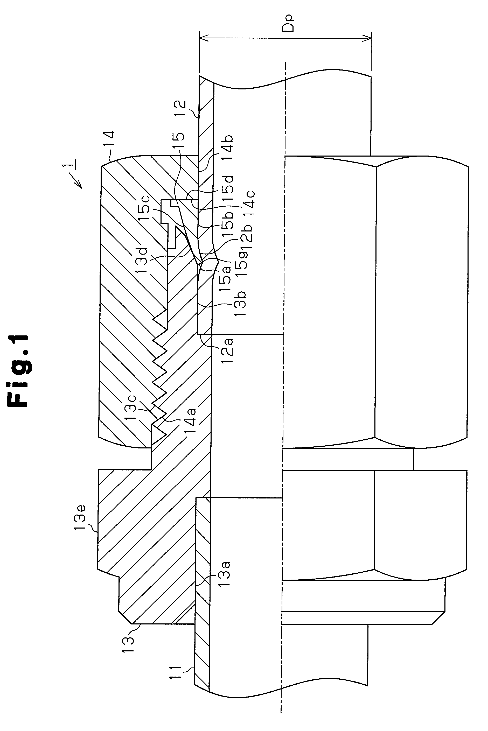
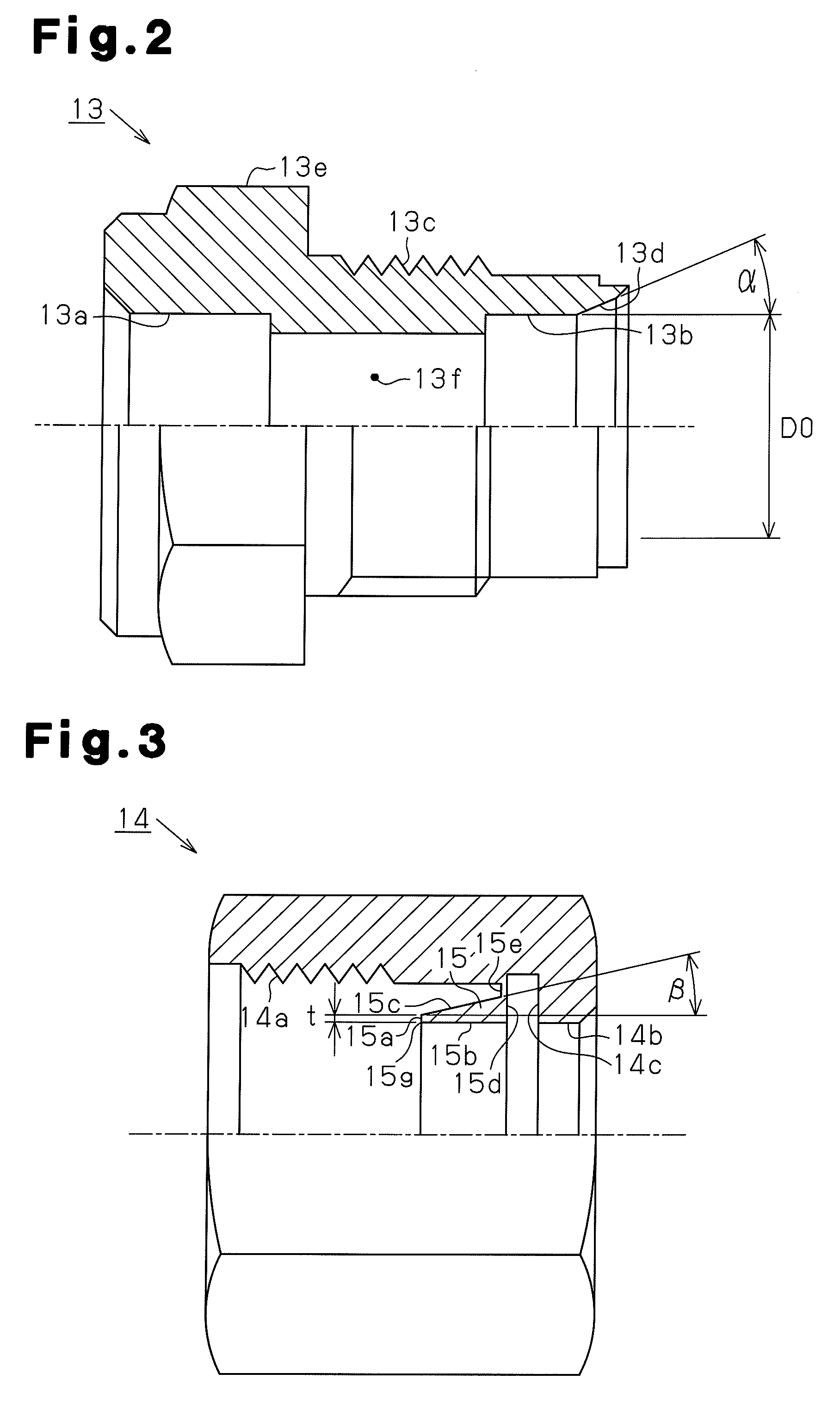
[0035]FIG. 1 is a partial cross-sectional view showing the construction of a pipe joint. The pipe joint 1 connects pipes 11 and 12, and has a joint body 13 having a cylindrical shape into which the pipes 11, 12 are inserted, a nut 14 as a fastening member threaded with the joint body 13, and a sleeve 15 which is interposed between the joint body 13 and the nut 14 at the pipe joining operation and has an annular shape. The pipe 11 is fixed to the joint body 13, for example, by brazing at a socket portion 13a formed at the distal portion of the joint body 13. The distal portion 12a of the pipe 12 to be connected to the joint body 13 is inserted into a joint hole 13b formed at, the proximal portion of the joint body 13. The distal portion 15a of the sleeve 15 bites into the outer peripheral surface 12b of the pipe 12 by the thread engagement between the nut 14 an...

second embodiment

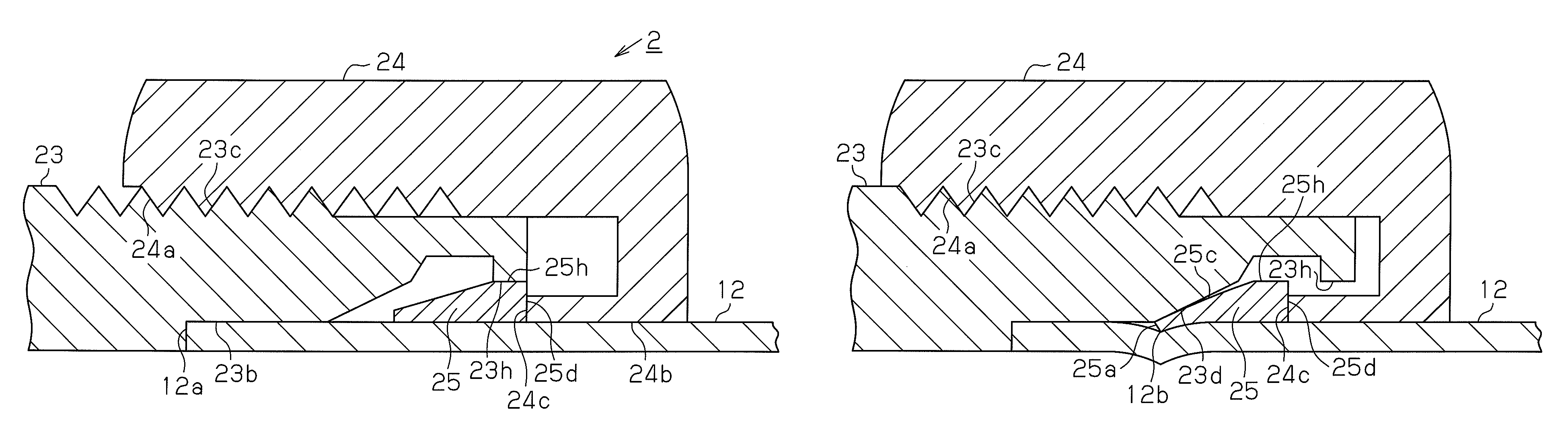
[0068]Next, a pipe joint according to a second embodiment of the present invention will be described with reference to FIGS. 6(a) to 6(c). In the second embodiment, the construction that the sleeve bites into the outer peripheral surface of the pipe by screwing the nut into the joint body and the pipe is joined to the joint body (see FIG. 1) is the same as the first embodiment. In the second embodiment, the sleeve 25 and the nut 24 are not integrated with each other, but the sleeve 25 and the joint body 23 are integrated with each other. That is, the sleeve 25 is integrated with the joint body 23 before the joining of the pipe 12, and the sleeve 25 is constructed to be cut off and separated from the joint body 23 by screwing the nut 24 as the fastening member into the joint body 23. Furthermore, the sleeve 25 is joined to the joint body 23 by a method such as adhesion or the like, whereby the sleeve 25 is integrated with the joint body 23. In the embodiment described below, the over...

third embodiment

[0080]Next, a pipe joint according to a third embodiment of the present invention will be described with reference to FIGS. 7(a) to 7(c). In the first and second embodiments, the pipe is joined to the joint body by the thread engagement between the nut and the joint body. In contrast, in the third embodiment and a fourth embodiment described below, the pipe is joined to the joint body without using any screw structure between the joint body and the nut. In the pipe joints according to the third and fourth embodiments, the sleeve is integrated with the fastening member. The sleeve is cut off from the fastening member by the sliding movement of the fastening member in the axial direction of the pipe, and the separated sleeve bites into the outer peripheral surface of the pipe. The overlapping description of the same constructions as the first embodiment such as the construction that the sleeve bites into the outer peripheral surface of the pipe, etc., is omitted or simplified.

[0081]FI...


PUM

PropertyMeasurementUnit
inclination angleaaaaaaaaaa
thicknessaaaaaaaaaa
pressureaaaaaaaaaa

Abstract

A pipe joint and a method of joining pipes using the pipe joint prevent loss of a sleeve, enhance workability in the pipe joining operation, and ensure sealing performance. The pipe joint may be utilized in a refrigerant device, a heat pump hot water supply device, a closing valve and a water supply piping. The method for connecting piping may be used in an in-the filed piping method. The pipe joint includes a joint body, a fastening member such as a nut, and a sleeve. The sleeve is integrated with the fastening member or the joint body before the fastening member is attached to the joint body. When the fastening member is attached to the joint body, the sleeve is cut off and separated from the fastening member or joint body. When the nut is fully attached, the sleeve bites into the pipe, and the pipe is joined to the joint body.

Description

CROSS-REFERENCE TO RELATED APPLICATIONS[0001]This U.S. National stage application claims priority under 35 U.S.C. §119(a) to Japanese Patent Application Nos. 2005-289209, filed in Japan on Sep. 30, 2005, and 2006-023471, filed in Japan on Jan. 31, 2006, the entire contents of which are hereby incorporated herein by reference.TECHNICAL FIELD[0002]The present invention relates to a pipe joint for joining, for example, a refrigerant pipe, a refrigeration device using the pipe joint, a heat pump hot water supply device using the pipe joint, a closing valve using the pipe joint, a water supply piping, a method for connecting piping, and an in-the-field piping method.BACKGROUND ART[0003]A pipe joint with which a pipe is inserted into a joint hole of a joint body and then a nut is screwed into the joint body to connect the pipe to the joint hole of the joint body has been known as a pipe joint used for joining of a pipe through which fluid is made to flow into a refrigerant pipe of a refri...

Claims


Application Information

Patent Timeline
Patent Type & Authority Patents(United States)
IPC IPC(8): F16L19/08
CPCF16L19/10F16L19/14F24H1/0081F24D17/02Y10T29/49934F24H1/54F25B41/00F16L19/08
Inventor NAKATA, HARUOMATSUOKA, HIROMUNETANAKA, JUNICHIROU
Owner DAIKIN IND LTD
Why Eureka
Try Eureka