Connector for linear members

a technology of connecting rods and linear members, which is applied in the direction of rod connections, couplings, balusters, etc., can solve the problems of limiting the design of guide rails and time-consuming work, and achieve the effects of simple structure, low cost and convenient construction

Inactive Publication Date: 2011-07-05
KIM MYOUNG SU
View PDF7 Cites 16 Cited by
  • Summary
  • Abstract
  • Description
  • Claims
  • Application Information

AI Technical Summary

Benefits of technology

[0011]According to the present invention, wall structures are easily constructed by assembling a plurality of linear members including pipes and bars in various patterns. Also, the connector according to the present invention has a simple structure, and thus the present invention can achieve lower costs.

Problems solved by technology

This is a time-consuming work and limits the design of the guide rails.

Method used


Image

  • Connector for linear members
  • Connector for linear members
  • Connector for linear members

Examples


Embodiment Construction

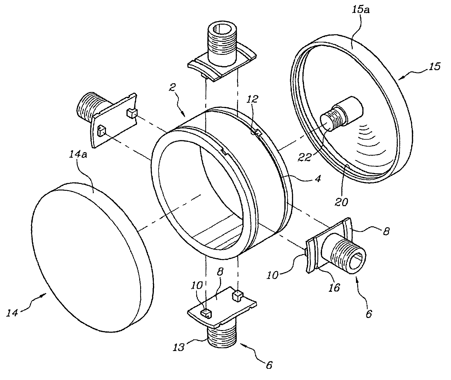
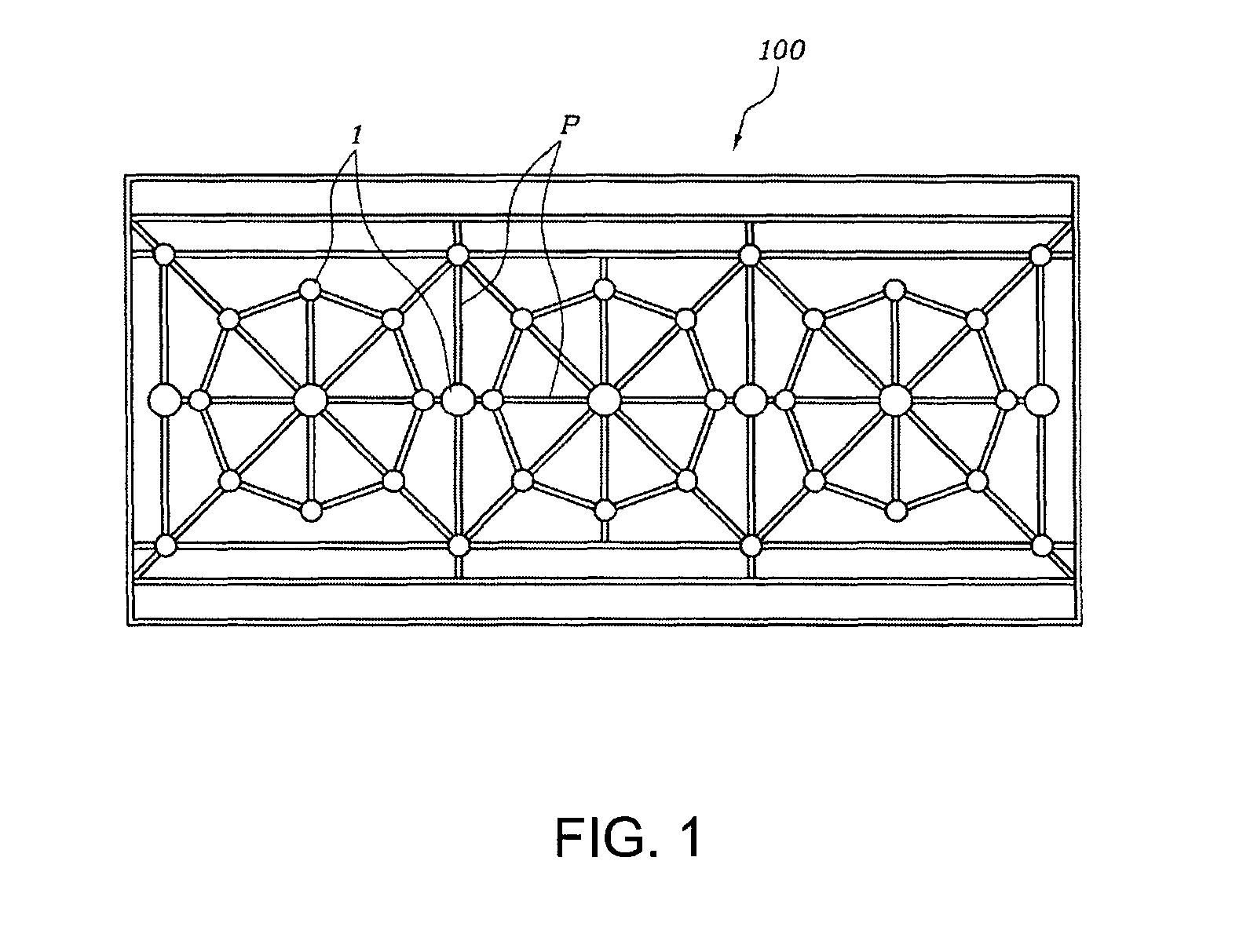
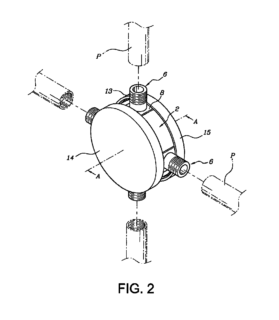
[0024]FIG. 1 is a front view of a guide rail constructed by the connectors of the present invention. FIG. 2 is a perspective view of a connector according to a first embodiment of the present invention. FIG. 3 is an exploded view of the connector shown in FIG. 2. FIGS. 4A and 4B are cross-sectional views of the connector taken from the line A-A in FIG. 2. FIG. 5 is a front view of the connector shown in FIG. 2. FIGS. 6A and 6B are cross-sectional views of a connector according to a second embodiment of the present invention. FIGS. 7A, 7B, 8A and 8B are cross-section views of the connectors according to a third and a forth embodiments of the present inventions. FIG. 9 is a front view of the connector according to another embodiment of the present invention. The connectors of the present invention are used in same applications as the connector 1 shown in FIG. 1.

[0025]A plurality of linear members are radially connected to the central body of annular shape. At least one socket member i...


PUM


Abstract

Connectors for linear members of wall structure which allows a variety of guide rails, fences, and pipes to be assembled in a desired pattern conveniently are provided. The connector includes a central body of annular shape; at least one socket member 6, the one end of the socket member being connected to the central body and the other end being connected to the linear member, such as pipe, wire or bar; and a rail means that connects the central body and the socket member such that the socket member can be moved along the circumferential surface of the central body.

Description

CROSS-REFERENCE TO RELATED APPLICATIONS[0001]This application claims priority to Korean Application No. 10-2008-0089624, filed on Sep. 11, 2008; the content of which is hereby incorporated by reference in its entirety.FIELD OF THE INVENTION[0002]The present invention relates to a connector, more specifically, a connector for linear members of wall structure which allows a variety of guide rails, fences, and pipes to be conveniently assembled in a desired pattern.BACKGROUND OF THE INVENTION[0003]Wall structures used for guard rails of stairs, guide rails for discriminating between a roadway and a footway, and fences for representing boundaries of land generally have posts that are vertically positioned at a distance and blocking members between the posts. Especially, lattices made by linear members, for example, bars and pipes, etc. are usually used.[0004]Recently, many of self-governing bodies use wall structures which are designed to present a fine sight or to represent symbols of ...

Claims


Application Information

Patent Timeline
Patent Type & Authority Patents(United States)
IPC IPC(8): F16D1/12
CPCE04F11/1844E04H17/16E04B1/585F16B7/185Y10T403/443Y10T403/7073Y10T403/349Y10T403/345Y10T403/32098Y10T403/32245E04H17/14E04F11/18F16B7/00
Inventor KIM, MYOUNG-SU
Owner KIM MYOUNG SU
Why Eureka
Try Eureka