Electrosurgical instrument with opposing jaws, central knife, and barbs for maintaining clamping tension on tissue even after opening jaws

a technology of surgical instruments and jaws, applied in the field of electrosurgical instruments, can solve the problems of increasing the risk of infection, promoting abrasive wear of cutting sections, and mechanical strain on cutting instruments, so as to reduce the force applied to cut vessels or tissues by means of cutting instruments, and reduce the risk of infection

Active Publication Date: 2011-07-05
ERBE ELEKTROMEDIZIN GMBH
View PDF11 Cites 31 Cited by
  • Summary
  • Abstract
  • Description
  • Claims
  • Application Information

AI Technical Summary

Benefits of technology

[0011]It is an object of the invention to provide an electrosurgical instrument wherein, with respect to conventional instruments, the force applied to cut a vessel or a tissue by means of a cutting instrument is reduced and, any mechanical strain on the cutting instrument, in particular any wear of cutting sections, is also reduced.

Problems solved by technology

With coagulation, a high-frequency current is passed through the tissue being treated, causing it to alter due to protein coagulation and dehydration.
With mechanical cutting, the surgeon must exert force in order to carry out the cut, which, on the one hand, produces a mechanical strain on the cutting instrument and, on the other, promotes abrasive wear of the cutting sections.
Also, as a result of such wear, particles of the cutting sections will remain in the tissue, causing an increased risk of infection.
A reduction in the expendable cutting force is effected with conventional cutting instruments, for example, by means of transmission mechanisms that are elaborate to manufacture and expensive.
Instruments of a large constructed size, however, are precisely unsuited to endoscopic procedures.
This requires an elaborate and expensive process.
In addition, the coated sections can only be inadequately reworked, that is to say, for example, reground.
To avoid reworking, the instruments, in particular the cutting sections, are often constructed as disposable or semi-reusable instruments, incurring high costs here, too.

Method used


Image

  • Electrosurgical instrument with opposing jaws, central knife, and barbs for maintaining clamping tension on tissue even after opening jaws
  • Electrosurgical instrument with opposing jaws, central knife, and barbs for maintaining clamping tension on tissue even after opening jaws
  • Electrosurgical instrument with opposing jaws, central knife, and barbs for maintaining clamping tension on tissue even after opening jaws

Examples


third embodiment

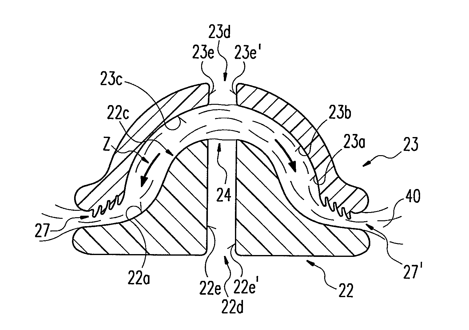
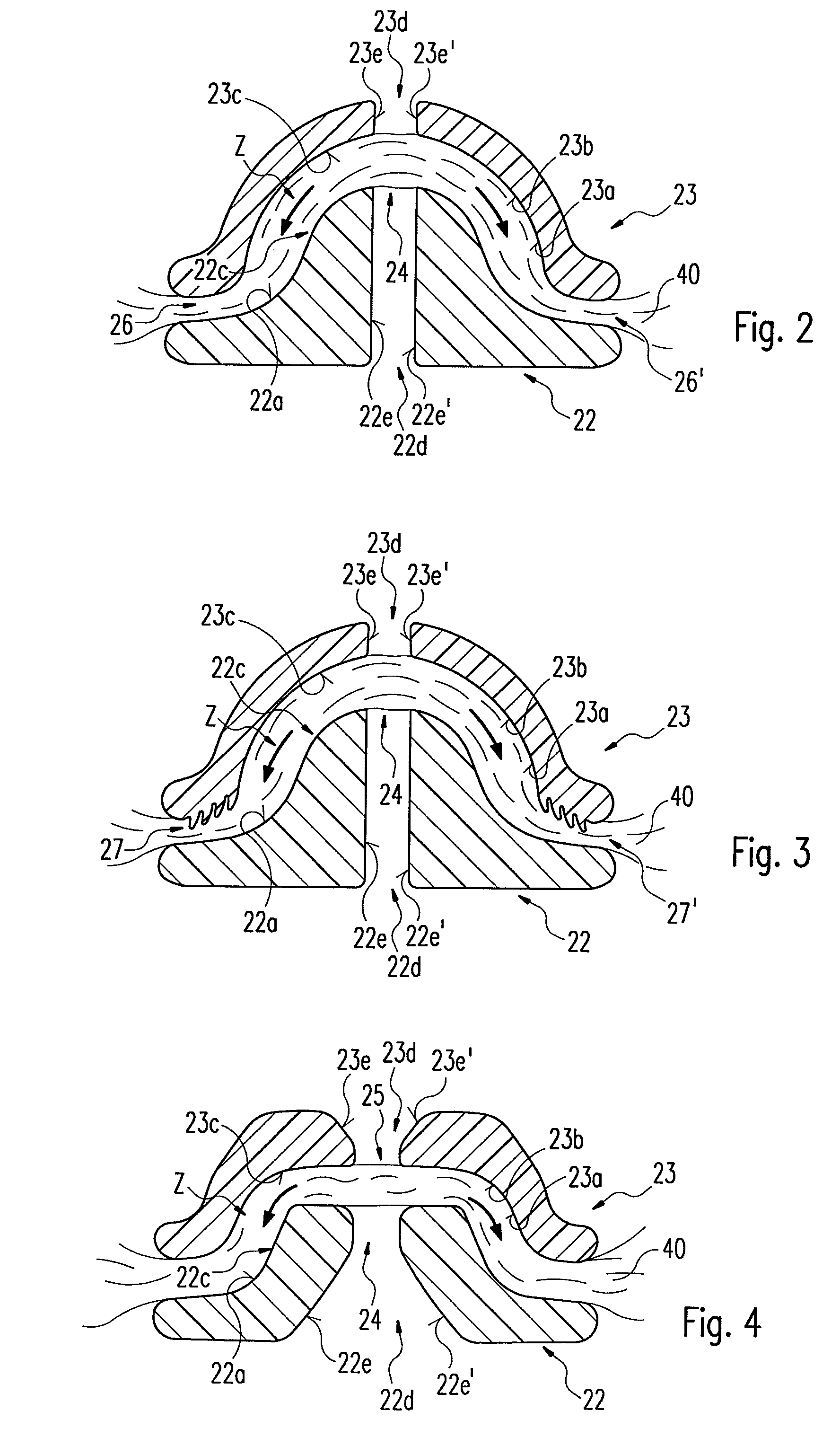
[0058]FIGS. 2 and 3 each depict a considerably enlarged front elevation of an electrode arrangement as a cross-section in a second and third embodiment respectively. The electrode parts 22, 23 correspond essentially to the embodiment of those depicted in FIG. 1. These also have passages 22d, 23d serving as a guide opening 24 for a cutting instrument as described in FIG. 1. A surface profile supporting a clamping effect of clamped tissue 40 is configured on at least one clamping region. The profile is preferably configured at both end areas of the respective clamping region or the respective clamping regions 22c, 23c and additionally moves the tissue 40 in a direction of traction Z defined by the clamping regions 22c, 23c or prevents any retreating of the tissue 40 against this direction of traction Z.

[0059]As depicted in FIG. 2, coagulating surfaces 22a, 23a of the electrode parts 22, 23 are formed at their two end areas in such a way that the tissue 40 is taken along in the directi...

fourth embodiment

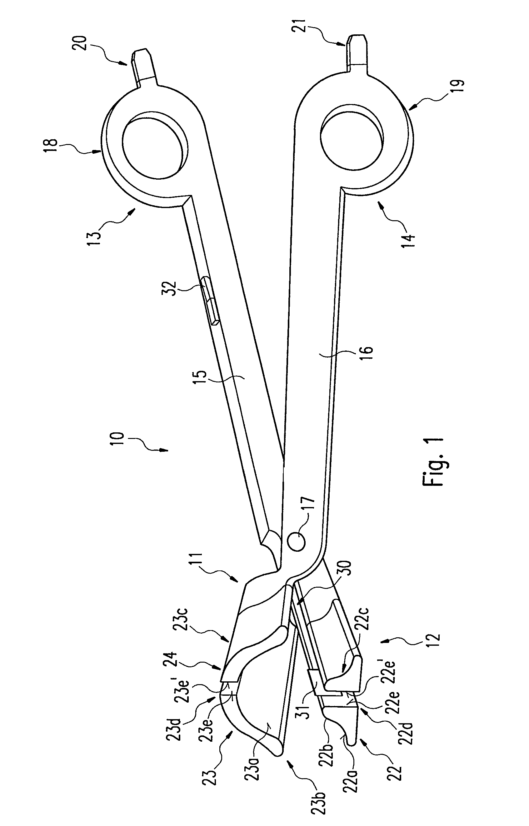
[0062]FIG. 4 depicts an enlarged front elevation of an electrode arrangement as a cross-section in a In this case, passages 22d, 23d divide the respective electrode parts 22, 23 into at least two areas in such a way that the electrode parts 22, 23 each have opposing split surfaces 22e, 22e′ and 23e, 23e′ arranged in a tapering manner relative to each other in the direction of the coagulating surfaces 22a, 23a. Since the split surfaces 22e, 22e′, 23e, 23e′ of the corresponding electrode parts 22, 23 converge on one cutting area 25, this further guarantees precise guidance of the cutting instrument 30 here. The part of the passages 22d, 23d directed away from the cutting area 25 is particularly suited to reprocessing, that is to a cleaning of the instrument 10 after a successful intervention or also to the subsequent application of a coating of the split surfaces 22e, 22e′, 23e, 23e′ with, for example, a wear-resistant layer of ceramic, since improved accessibility is guaranteed due ...

fifth embodiment

[0063]FIG. 5 depicts an enlarged front elevation of an electrode arrangement as a cross-section in a This embodiment corresponds essentially to the one depicted in FIGS. 1 and 2. The difference is that clamping regions 22c, 23c are configured here with different radii of curvature; the radius of curvature of the concavely configured clamping region 23c is larger than the radius of curvature of the convexly configured one. As a result, the respective coagulating surfaces 22a, 23a are also correspondingly curved. The curvatures 22b, 23b run around longitudinal axes of the distal ends in such a way that tissue 40 held between the distal ends 11, 12 and running perpendicular to the longitudinal axes is held with increasing compression relative to central sections of the clamping regions 22c, 23c. Advantageously, tissue 40 once clamped here is arrested particularly securely between the clamping regions 22c, 23c due to the increasing compression. Any sliding of the tissue 40, once graspe...


PUM


Abstract

The invention concerns an electrosurgical instrument comprising two articulated limbs, which can be actuated in the manner of a cutting or a clamping tool. The instrument further comprises opposing electrode parts with coagulating surfaces at the distal ends of the limbs for grasping a vessel or tissue and for conducting a coagulating current through the vessel or tissue in order to cause it to coagulate, as well as current-supplying devices for supplying the coagulating current to the electrode parts from a HF generator. In addition, the electrode parts each have at least one clamping region, such that clamped tissue is pretensioned between the electrode parts in order that a cutting procedure can be carried out on the pretensioned tissue by means of a cutting instrument.

Description

RELATED U.S. APPLICATIONS[0001]Not applicable.STATEMENT REGARDING FEDERALLY SPONSORED RESEARCH OR DEVELOPMENT[0002]Not applicable.REFERENCE TO MICROFICHE APPENDIX[0003]Not applicable.FIELD OF THE INVENTION[0004]The invention concerns an electrosurgical instrument comprising two limbs that have an articulated connection and that can be actuated in the manner of a cutting or clamping tool.BACKGROUND OF THE INVENTION[0005]Electrosurgical instruments have been used for many years in high-frequency surgery, in particular to coagulate biological tissue, as well as to cut it. With coagulation, a high-frequency current is passed through the tissue being treated, causing it to alter due to protein coagulation and dehydration. The tissue contracts in such a way that the vessels occlude and bleeding is staunched. Once coagulation has occurred, the tissue can be cut through, for example, by means of a mechanically operating cutting instrument.[0006]Electrosurgical procedures can be carried out ...

Claims


Application Information

Patent Timeline
Patent Type & Authority Patents(United States)
IPC IPC(8): A61B18/14
CPCA61B18/1442A61B2018/1412A61B2018/1455
Inventor HAFNER, DIETER
Owner ERBE ELEKTROMEDIZIN GMBH
Why Eureka
Try Eureka