Means for drying of a particulate material with a gas

a technology of drying method and particulate material, which is applied in drying machine, drying machine with progressive movement, lighting and heating apparatus, etc., can solve the problems of large amount of gas required, large dust formation and fire hazards, and high heating and operating energy consumption

Inactive Publication Date: 2012-02-16
ANG BYHAMMAR TOMAS
View PDF4 Cites 2 Cited by
  • Summary
  • Abstract
  • Description
  • Claims
  • Application Information

AI Technical Summary

Benefits of technology

[0015]Unique for the invention is that the material moves downwards while it is carried by the walls through screw line ramps (to maintain the porosity) as well as contributes to revolving the movable wall through influence of the weight of the material as well as by the screw ramps and that the rotation can be assisted by means of the movable wall, is given an axial upwards and downwards movement. Effects of this are that the mechanical strains on the turning wall are significantly reduced when the torque moment is locally generated near the friction surfaces instead of externally.

Problems solved by technology

All in all, the systems of today lead to high consumption of heating and operating energy, large dust formation and fire hazard.
At drying with low temperature or with low temperature difference, large amounts of gas is however required to add the required heat and to remove residue products, for example moisture.
If a person chooses to work with high gas speed at the contact between gas and material so that the material is transported with the gas, a large amount of dust will follow the gas out of the apparatus, also after use of fairly costly separating systems.
Further, a significant ventilation work is required to perform the process.
A disadvantage with these is that they will require a lot of space and that laying operations, transport and gathering of the material require a lot of mechanical equipment.
To reduce these problems, people are tempted to use relatively deep beds which leads to large pressure fall for the gas and thereby a demand for a lot of electric energy to fuel the ventilating fans.
The increasing height also leads to increased strains on the transportation equipment since the moist material at increased storage height is increasingly more difficult to transport.
If a person instead chooses to work with a vertical bed and a horizontal gas flow, several undesired phenomena will occur.
The height also leads to that the porosity in the drying material is reduced, which in turn leads to larger pressure drops and an uneven distribution of the passing gas.
The adhesion between the particles, foremost for fibrous and long granulated material leads to a strong tendency to create aggregates and bridges that disturb or prevent the movement of the material.
Since a bridge often is balanced by an empty space or an area with higher porosity under the bridge, also this phenomenon leads to an uneven distribution of the gas that passes through the material.

Method used


Image

  • Means for drying of a particulate material with a gas
  • Means for drying of a particulate material with a gas
  • Means for drying of a particulate material with a gas

Examples


Embodiment Construction

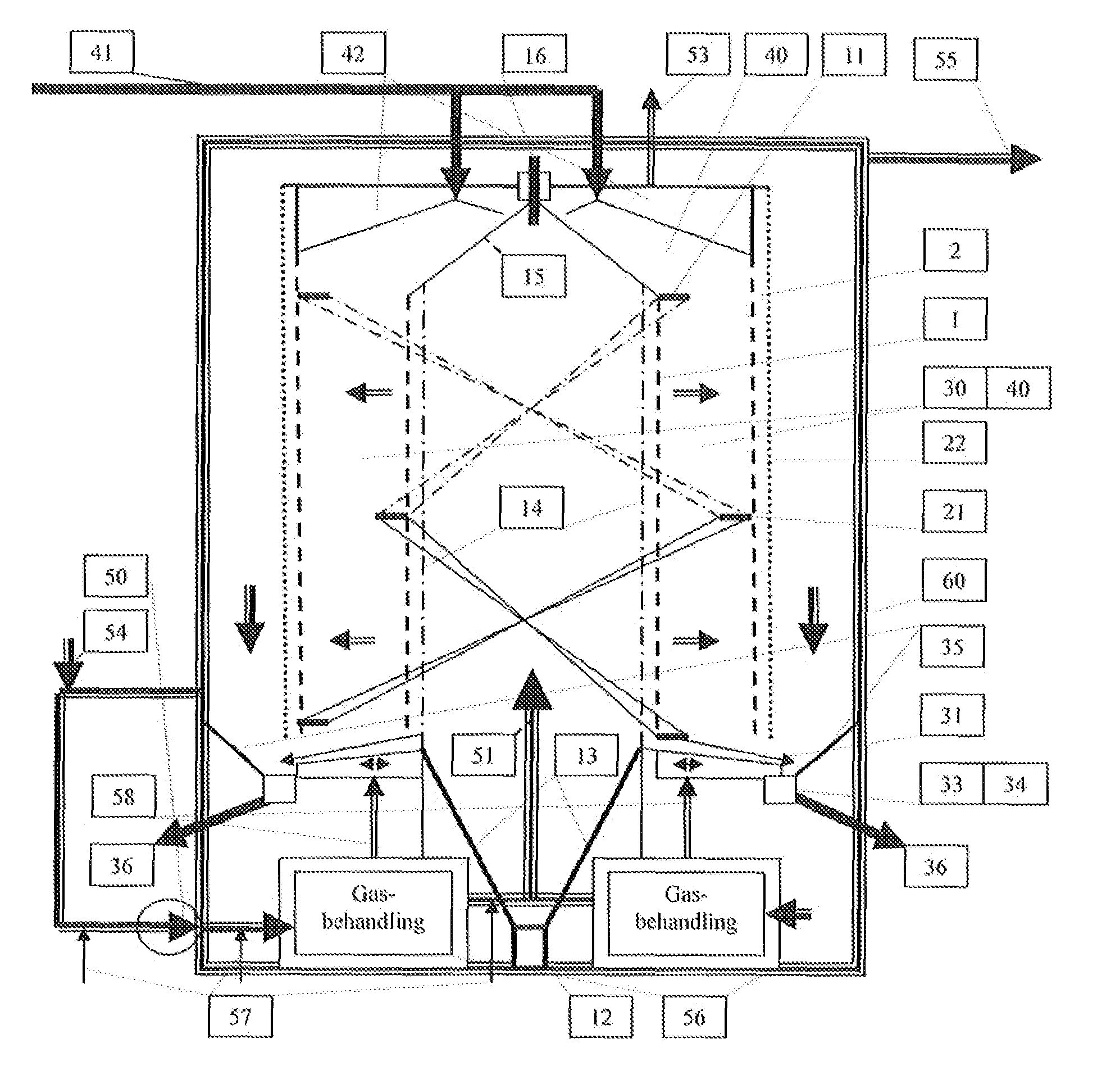
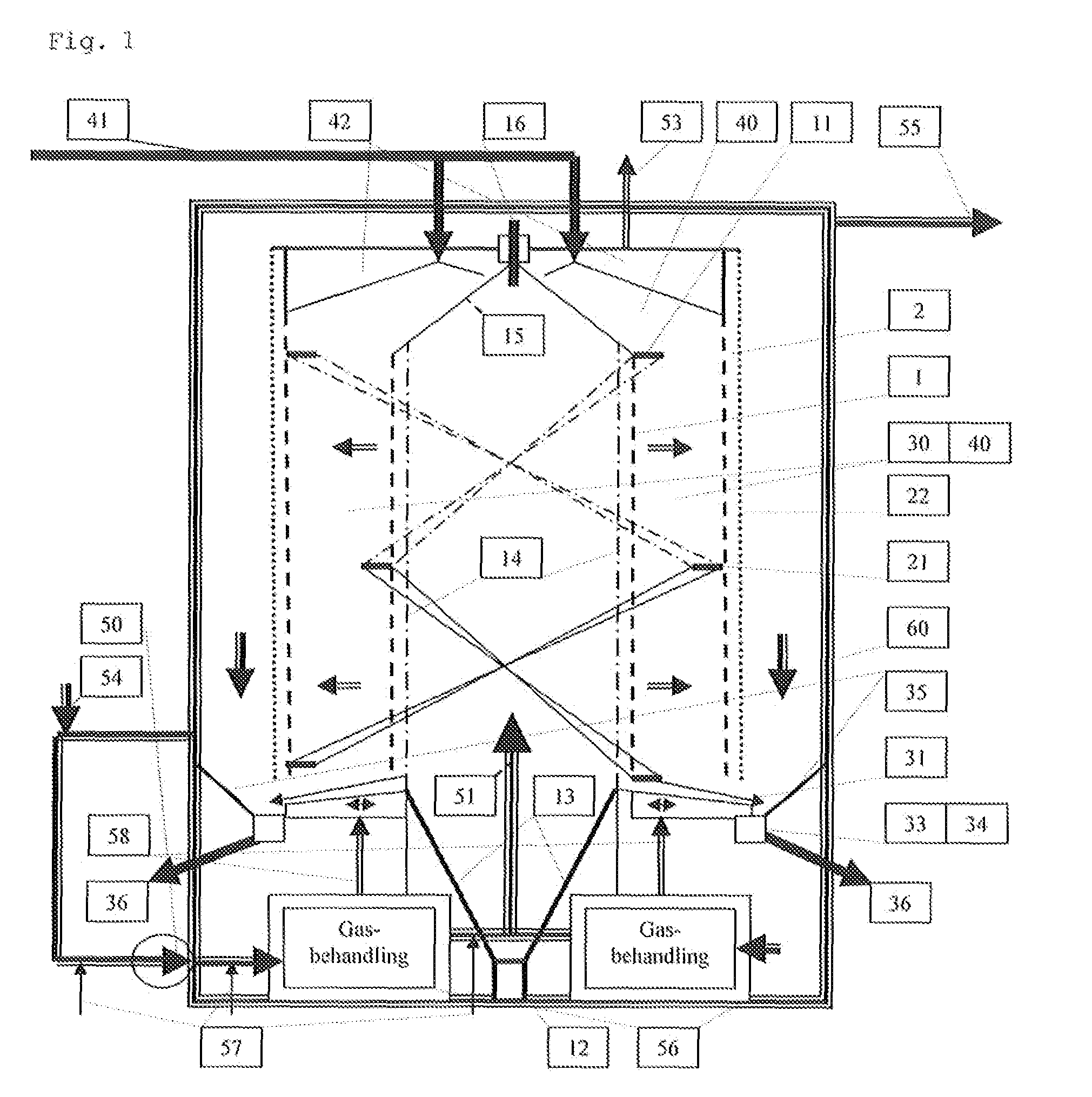
[0017]FIG. 1 shows a schematic axial section through a first embodiment of a drying device according to the invention which comprises a hole cylindrical (tubular) shaft 30, which is defined by two coaxial tubular elements 1, 2 which are arranged permeable by gas, but not or only partly for a particulate material 40, which is received in the tubular shaft 30 between the walls 1, 2. Over the shaft is a storage space 42 with delivery lines for material that is to be treated (drying goods). The storage room is always filled so that a cavity in the shaft immediately can be filled with new material. The bottom of the shaft is constituted by an output disc 31, that is arranged to release material in a controlled manner from the lower end of the shaft 30 to a collecting vessel 33, that has a device for tangential transportation 34 towards one or several outlets 36. The bottom consists of one or several ring discs 31, which are separately rotating around the axis of the drying device or radi...


PUM


Abstract

A device to bring a gas into contact with a particulate solid bulk material, comprising a first and a second tubular, radially gas-permeable element (1, 2) having different diameters and which each define a central axis, wherein one of the elements is essentially coaxially placed in the second element, wherein the elements (1, 2) internally define a ring-shaped shaft (30) for a material (40) that is to be contacted by the gas, wherein the elements have essentially vertically oriented axes, a ventilation device (50) for compelling the gas radially through the shaft and the material, a first device (41) for addition of the material to an upper end of the shaft (30) and a second device (31-36) for output of dried material from the lower end of the shaft. Driving means (12) are provided for internal displacement of the elements (1, 2). At least one of the walls is provided with at least one screw line ramp which maintains a high porosity and a controlled feeding of the material.

Description

TECHNICAL FIELD OF THE INVENTION[0001]The invention relates to a device according to the preamble of the appended independent device claim.[0002]The invention thus relates to a device, by which a particulate bulk material is brought into direct contact with a flow of gas for transmitting material and energy.PRIOR ART[0003]Treatment of a solid material with large amounts of gas takes place in several industrial processes, especially at drying of moist material such as barque, shingle, grain, malt, fermenting residues, animal feed, foodstuff and mud. Here is by dryer intended a device where a solid material is affected by contacting a tempered gas with a solid material to attain a desired process in the solid material, for example drying, adsorption, evaporation, cooling, germination, roasting, torrefaction etc. If the gas contains hot steam, especially water steam, the material can be effectively heated and / or moisturized in the contact with this hot steam. By steam and moist is here...

Claims


Application Information

Patent Timeline
Patent Type & Authority Applications(United States)
IPC IPC(8): F26B15/26
CPCF26B17/124F26B17/22
Inventor ABYHAMMAR, TOMAS
Owner ANG BYHAMMAR TOMAS
Why Eureka
Try Eureka