
Heat preservation cylinder clamping groove device for sintering furnace

A technology for a sintering furnace and a heat preservation cylinder, which is applied in the field of sintering furnace parts, can solve the problems of huge engineering volume, high cost, damage of the heat preservation cylinder, etc., and achieves the improvement of service life and stability, low cost, and reduction of use damage. Effect

Active Publication Date: 2020-04-21
ZHUZHOU RUIDEER METALLURGICAL EQUIP MFG CO LTD
View PDF5 Cites 2 Cited by
  • Summary
  • Abstract
  • Description
  • Claims
  • Application Information

AI Technical Summary

Problems solved by technology

Because this kind of sintering furnace is a high-pressure furnace, the high-pressure airflow in the furnace will wash the insulation cylinder, and the multi-layered carbon felt at both ends of the insulation cylinder has no resistance to the high-pressure airflow. This phenomenon will cause great damage to the insulation cylinder. damage
When the insulation cylinder is damaged to a certain extent, the replacement of the insulation cylinder is not only a huge amount of work but also a high cost

Method used


Image

  • Heat preservation cylinder clamping groove device for sintering furnace
  • Heat preservation cylinder clamping groove device for sintering furnace
  • Heat preservation cylinder clamping groove device for sintering furnace

Examples


Embodiment Construction

[0041] The technical solutions of the present invention will be further described below in conjunction with the accompanying drawings and through specific implementation methods.

[0042] Wherein, the accompanying drawings are only for illustrative purposes, showing only schematic diagrams, rather than physical drawings, and should not be construed as limitations on this patent; in order to better illustrate the embodiments of the present invention, some parts of the accompanying drawings will be omitted, Enlargement or reduction does not represent the size of the actual product; for those skilled in the art, it is understandable that certain known structures and their descriptions in the drawings may be omitted.

[0043] In the drawings of the embodiments of the present invention, the same or similar symbols correspond to the same or similar components; , "inner", "outer" and other indicated orientations or positional relationships are based on the orientations or positional ...


PUM


Abstract

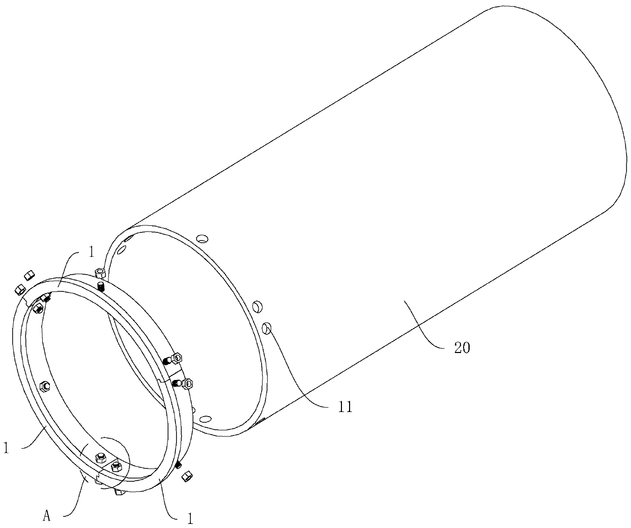
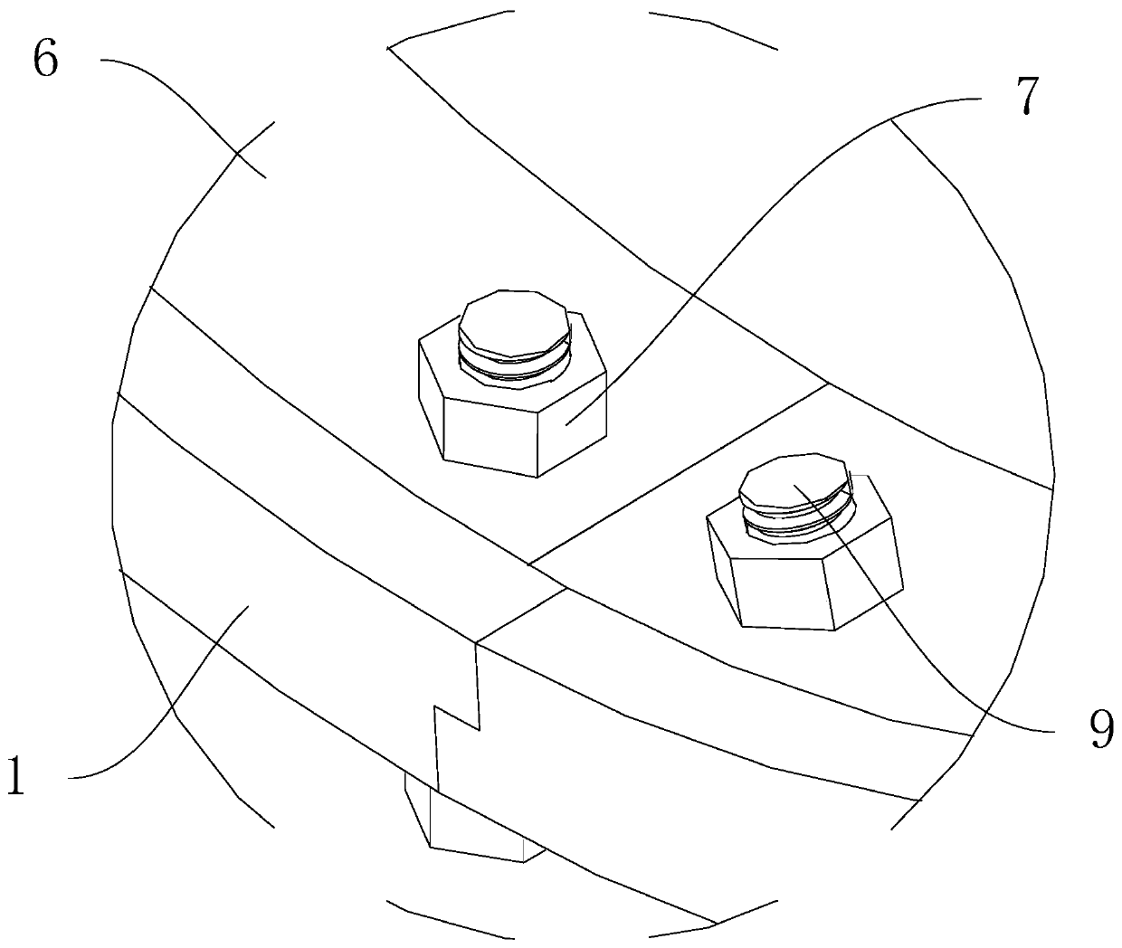
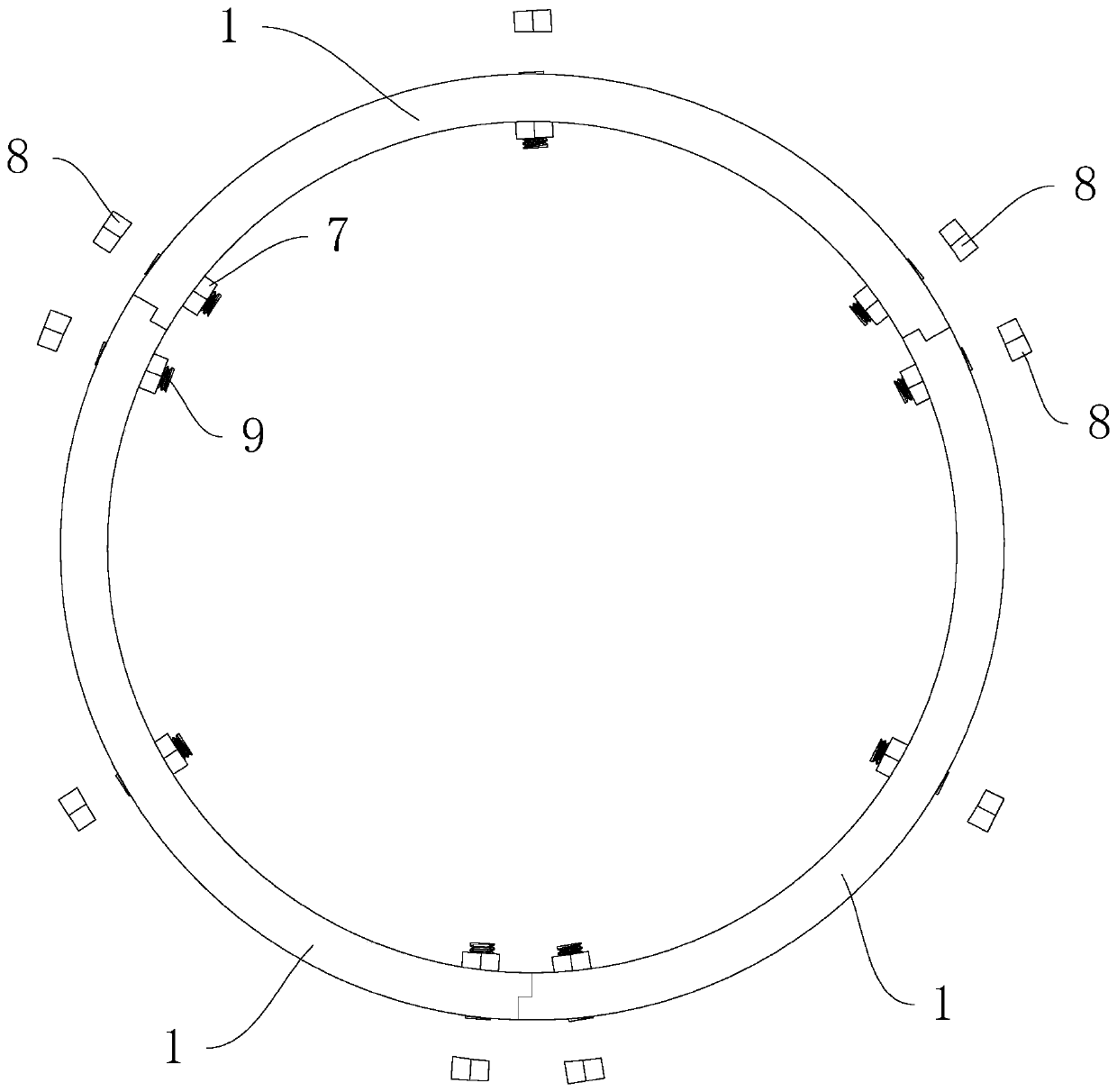
The invention belongs to the technical field of sintering furnace parts and relates to a heat preservation cylinder clamping groove device for a sintering furnace. The device comprises a plurality ofend face clamping strips which can be spliced with one another; all the end face clamping strips can be spliced into an annular support coaxial with a heat preservation cylinder; the inner diameter ofthe annular support is smaller than that of the heat preservation cylinder; one side face of each end face clamping strip can be tightly attached to the end face of the heat preservation cylinder, wherein the side face of each end face clamping strip a sealing face; the sealing faces of the end face clamping strips are provided with flow-resisting blocking edges extending in the axial direction of the heat preservation cylinder; the flow-resisting blocking edges can be spliced with one another to form a flow-resisting ring which is coaxial with the annular support and is attached to the innersurface of the end part of the heat preservation cylinder; the flow-resisting blocking edges are curved strips; the inner arc surface of each of the flow-resisting blocking edges can be closely adhere to the inner wall surface of the heat preservation cylinder through a locking mechanism. According to the heat preservation cylinder clamping groove device for the sintering furnace of the invention, the use damage of the heat preservation cylinder can be decreased, and therefore, the stability of the heat preservation cylinder can be improved, and the service life of the heat preservation cylinder can be prolonged.

Description

technical field [0001] The invention relates to the technical field of sintering furnace parts, in particular to an insulating tube clamping groove device for a sintering furnace. Background technique [0002] With the vigorous development of my country's metallurgical industry, higher requirements have emerged for metallurgical equipment, including higher requirements for the service life and thermal insulation performance of metallurgical equipment. The insulation cylinder is one of the main parts of the sintering furnace, which will affect the important performance and service quality of the sintering furnace. [0003] The insulation cylinder is composed of multiple layers, and its main material is carbon felt composite material. The main function of the insulation cylinder is to minimize the heat dissipation loss of the heating element and improve the heating conditions in the furnace. Because this kind of sintering furnace is a high-pressure furnace, the high-pressure...

Claims


Application Information

Patent Timeline
IPC IPC(8): F27D1/00
CPCF27D1/00F27D2001/0069F27M2003/04
Inventor 李应新
Owner ZHUZHOU RUIDEER METALLURGICAL EQUIP MFG CO LTD
Learn More