Method for detaching wafers from a wafer carrier and device for this purpose

Inactive Publication Date: 2011-09-01
GEBR SCHMID GMBH & CO
View PDF7 Cites 2 Cited by
  • Summary
  • Abstract
  • Description
  • Claims
  • Application Information

AI Technical Summary

Benefits of technology

[0005]The invention is based on the object of providing a method cited at the beginning and a device cited at the beginning for performing the method, using which disadvantages of the prior art may be remedied and a lower mechanical strain of the wafers can be achieved in particular.
[0008]Thus, in an advantageous embodiment variant of the invention, the carrier unit is moved with the wafers in a uniform movement plane, so that no vertical acceleration forces act thereon. The ungluing basin is more or less provided and / or constructed around the wafers and closed. After the ungluing, the ungluing basin is again opened or disassembled and the wafers are moved further and / or moved away in a uniform movement plane. Means are advantageously provided on the carrier unit in order to still hold the detached wafers, which are no longer glued in place, and / or prevent falling down with possible danger of damage. This will be discussed in greater detail hereafter.
[0012]The two movable side wall parts pointing in the movement direction may advantageously be moved synchronously together. For this purpose, for example, a single mechanically coupled drive can be provided. In a further embodiment of the invention, it is possible that when the wafers are moved into the ungluing basin and when they are moved out, only the side wall part respectively standing in the way is moved away, or advantageously this side wall part is moved together with the corresponding side wall part on the other side. A drive mechanism can thus be kept comparatively simple with good functionality. The other two side wall parts are advantageously also implemented as movable, but they do not have to be moved away and / or lifted each time, but rather only for maintenance or inspection work, for example. Furthermore, a base of the ungluing basin, against which the side wall parts press in sealing fashion to close the ungluing basin, can be rigid and / or immobile. Advantageously, openable flaps or drains may be provided thereon, using which the solvent can be drained, so that uncontrolled solvent outflow does not occur when the side wall parts are moved away.
[0014]In another embodiment of the invention, it can be provided that the carrier unit with wafers is unglued and / or moved into the ungluing basin and the entire ungluing unit so that the wafers do not hang fixed and / or are not glued to the carrier unit by their upper side edge, but rather by a lower side edge. The wafers then more or less stand on the glued side edge. This has the advantage that after ungluing and / or dissolving of the adhesive, no movement or slipping of the wafers occurs, rather they remain standing on the same side edge. This also additionally reduces the mechanical strain and danger of damage.

Problems solved by technology

This vertical movement of the wafers on the carrier unit is viewed as disadvantageous, because it represents a mechanical strain.

Method used


Image

  • Method for detaching wafers from a wafer carrier and device for this purpose
  • Method for detaching wafers from a wafer carrier and device for this purpose
  • Method for detaching wafers from a wafer carrier and device for this purpose

Examples


Embodiment Construction

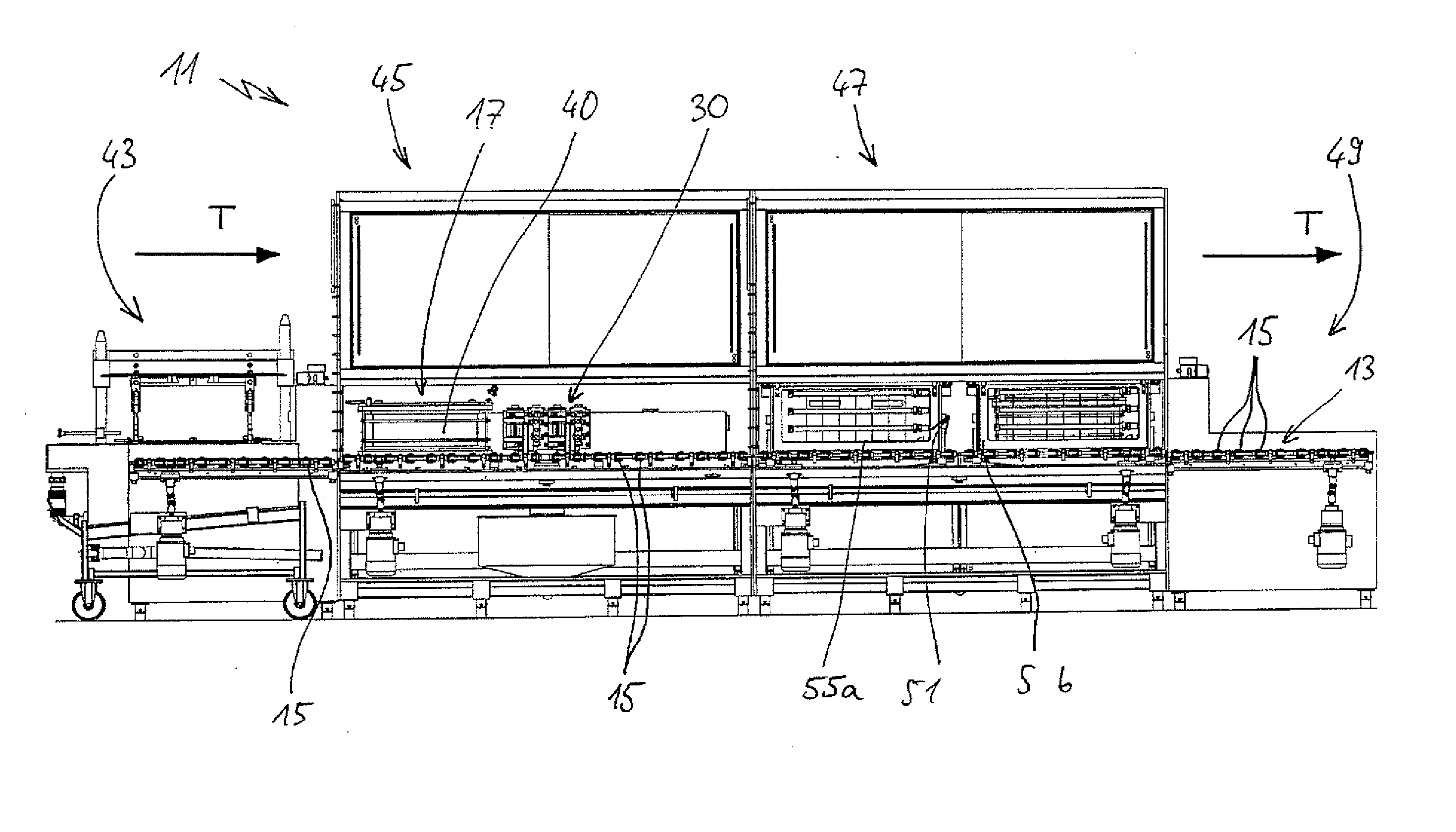
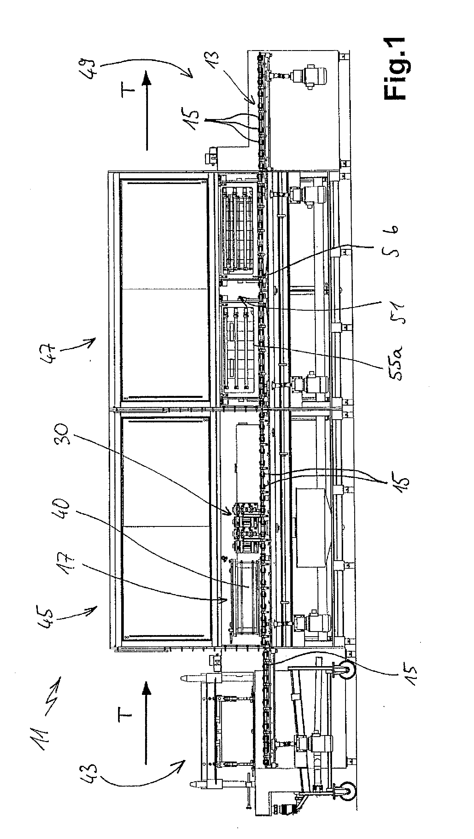
[0023]FIG. 1 shows a side view of an entire device 11 according to the invention, in which not only the cleaning of a sawn wafer block 40 occurs, but rather above all also the ungluing according to the invention, i.e. the detachment of the individual sawn wafers from the beam and / or the longitudinal carrier of the carrier units 17, to which they are still glued. The device 11 advantageously has chambers enclosing them. On the far left, it has an insertion module 43, using which the cage-like carrier units 17 with wafer blocks 40 therein are brought to the device 11 and then introduced. It can be seen that the insertion module 43 has rollers 15, which form a roller conveyor at the height of the transport conveyor 13 with the other rollers 15. The rollers are advantageously driven individually or as a whole. The previously described uniformly horizontal transport of the wafer blocks 40 can thus also be performed here.

[0024]A cleaning module 45 is implemented, as can be recognized and ...


PUM


Abstract

In a method for detaching wafers from a carrier unit, the wafers being formed by sawing a wafer block fastened to the carrier unit by gluing, and the wafers themselves still being glued on one side, the carrier unit with the wafers is introduced into an ungluing unit along a uniform movement plane. It remains therein and is enclosed in an ungluing basin by movable wall parts. Solvent for ungluing is applied into the ungluing basin and onto the wafers after the formation and closing of the ungluing basin to dissolve the glued bond and subsequently detach the wafers from the carrier unit.

Description

CROSS-REFERENCE TO RELATED APPLICATIONS[0001]This application is a continuation of PCT Application No. PCT / EP2009 / 063292, filed Oct. 12, 2009, and claims priority to DE 10 2008 053 598.2 filed Oct. 15, 2008, the disclosures of which are hereby incorporated by reference in their entirety.FIELD OF USE AND PRIOR ART[0002]The invention relates to a method for detaching wafers from a carrier unit and / or a so-called beam fastened to a carrier unit, the wafers being formed by sawing a wafer block glued to the carrier unit and / or the beam and still being glued on one side to the carrier unit. The invention also relates to a device for performing this method.[0003]Gluing a wafer block to a beam and then fastening this beam to a carrier unit is known from DE 10 2008 028 213 A. The wafer block can then be transported for further processing using the carrier unit. In particular, the wafer block is sawn into individual thin wafers, the upper edge of the wafers still being glued to the beam. Afte...

Claims


Application Information

Patent Timeline
IPC IPC(8): B23P19/02
CPCB28D5/0082Y10T29/49821Y10T29/53C09J5/06H01L21/67092H01L21/67126H01L21/6776
Inventor LAMPPRECHT, JORGPLAUELN, DIRKWOLBER, GERHARDWOLBER, LECHENWOLBER, MICHAELWOLBER, HANS-JORG
Owner GEBR SCHMID GMBH & CO
Why Eureka
Try Eureka