Nosewheel control apparatus

a control apparatus and nosewheel technology, applied in the direction of instruments, actuated personally, analogue processes for specific applications, etc., can solve the problems of poor machine efficiency and provision of torqu

Inactive Publication Date: 2011-07-12
BOREALIS TECH LTD
View PDF3 Cites 62 Cited by
  • Summary
  • Abstract
  • Description
  • Claims
  • Application Information

AI Technical Summary

Benefits of technology

[0042]It can be seen from the foregoing that it would be advantageous to be able to drive an aircraft on the ground using cockpit controls. It would be further advantageous to be able to drive an aircraft on the ground using controls on the ground within an airport, and to be able to transfer control between controllers.

Problems solved by technology

The use of small compact electric motors inside, or in close proximity to, an aircraft wheel, for direct drive, presents a problem relating to the provision of the required amounts of torque.
The active materials of the machine will be underutilized, the machine will be far heavier than necessary, and the machine efficiency will be poor.
This presents a significant problem, because, in these cases, the wheels may be rotating faster than the motor and may accelerate the motor via the gearing system.
However, this magnetic field configuration induces substantial rotor currents in the rotor windings, and the currents produce induction based torque to rotate the rotor.

Method used


Image

  • Nosewheel control apparatus
  • Nosewheel control apparatus
  • Nosewheel control apparatus

Examples


first embodiment

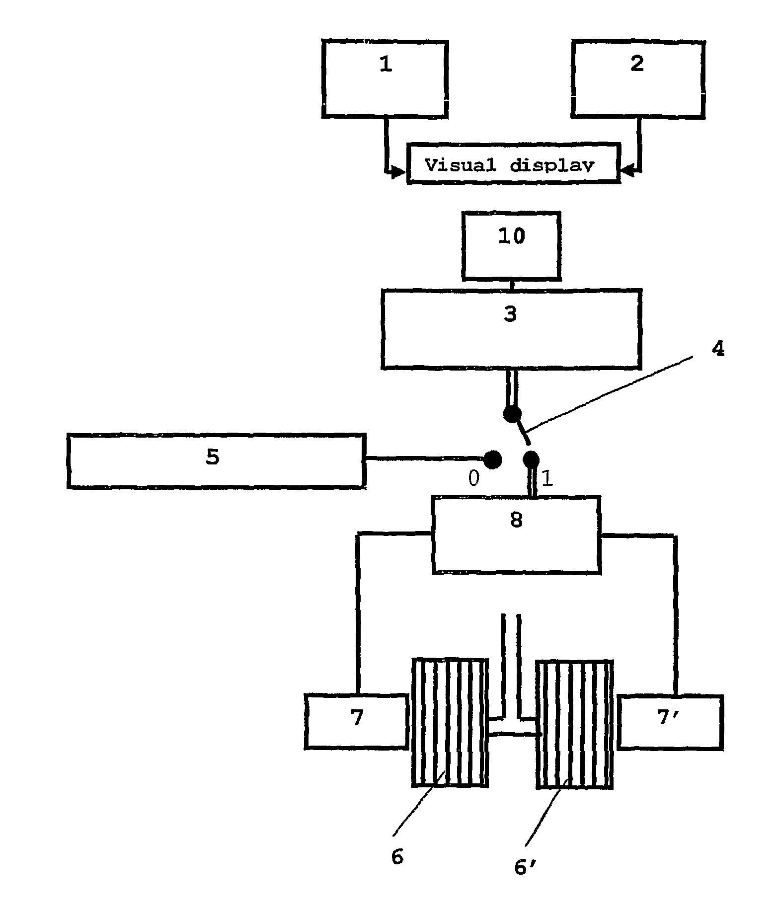
[0051]the present invention comprises, in an aircraft, two self-propelled nosewheels, each having an electric motor; equipment for flight; dual-function controlling means for controlling said equipment for flight and said nosewheels, said dual-function controlling means being disposed in the cockpit of said aircraft; a motor controller; sensing means; a visual display disposed in said cockpit; a toggle switch; and switching means. This may be better understood by reference to FIG. 1, which shows two nosewheels 6, 6′ each propelled by an electrical motor 7, 7′. Each motor is connected to the motor controller 8. Switching means 4 are switchably connected to the motor controller and to equipment for flight 5, and permanently connected to cockpit controlling means 3.

[0052]The dual function controlling means are switchably connected both to said equipment for flight and to the motor controller. The dual-function controlling means controls the equipment for flight when in flight and the n...

second embodiment

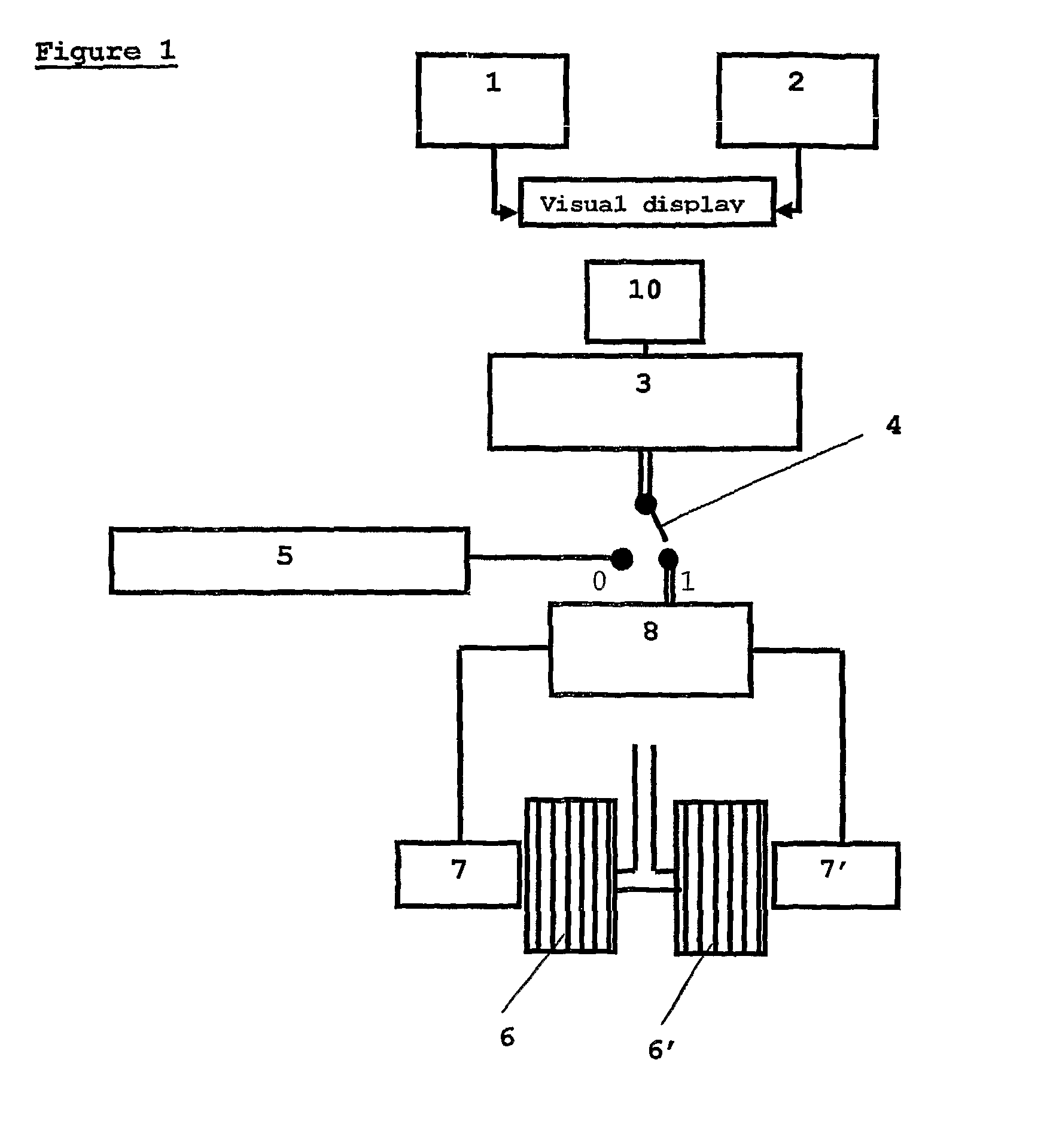
[0053]In the present invention, sensing means 1 is able to sense when the aircraft is on the ground. This may be better understood by reference to FIG. 2, which shows two nosewheels 6, 6′ each propelled by an electrical motor 7, 7′. Each motor is connected to the motor controller 8. Switching means 4 are switchably connected to the motor controller and to equipment for flight 5, and permanently connected to cockpit controlling means 3. According to this embodiment, the dual-function controlling means controls the equipment for flight when in flight and the nosewheel during taxi. Sensing means 1 is connected to switching means 4 via dual-function controlling means 3 and senses when the aircraft is on the ground. Further sensing means 2 may be connected to switching means 4 via dual-function controlling means 3 and may sense when aircraft is on the ground. Switching means 4 are connected to the equipment for flight when switching means 4 are off and to the nosewheels when switching me...

third embodiment

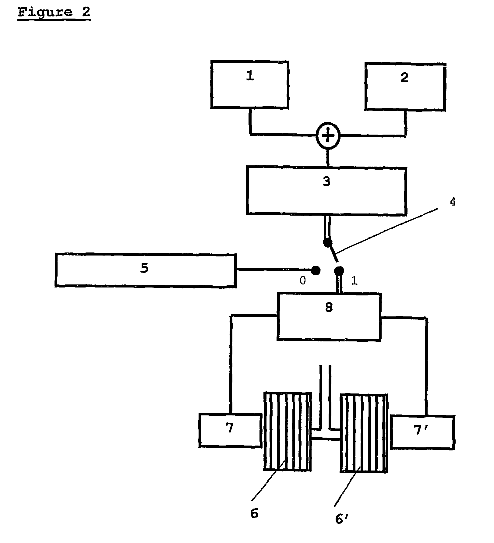
[0076]present invention preferably comprises two self-propelled nosewheels; equipment for flight; dual-function controlling means for controlling said nosewheels and said equipment for flight, having at least a first side operation and a second side operation; sensing means; and switching means. The dual-function controlling means are switchably connected to both the equipment for flight and the nosewheels. As shown in FIG. 3, sensing means 1 and sensing means 2 are connected to switching means 4 via dual-function controlling means 3. When the sensing means indicate that the aircraft is on the ground, switching means 4 connects rudder pedals 3 to nosewheels 6. When the sensing means indicate that the aircraft is in flight, switching means 4 connect dual-function controlling means 3 to equipment for flight 5. The dual-function controlling means 3 control the equipment for flight during flight and the nosewheel during taxi. At least one sensing means 1, 2 senses when the aircraft is o...


PUM


Abstract

An apparatus for driving a taxiing aircraft is disclosed, comprising, in an aircraft, two self-propelled nosewheels, each having an electric motor; equipment for flight; dual-function controlling means for controlling said equipment for flight and said nosewheels, said dual-function controlling means being disposed in the cockpit of said aircraft; sensing means; and switching means, —wherein said switching means are operable to switch the function of said dual-function controlling means between controlling said equipment for flight and controlling said nosewheels. Said dual function controlling means may control speed and / or steering of the aircraft. Second controlling means may be provided, and may be disposed externally to the aircraft.

Description

CROSS-REFERENCE TO RELATED APPLICATIONS[0001]This application is the U.S. national stage application of International Application No. PCT / US2006 / 033503, filed Aug. 29, 2006, which international application was published on Mar. 8, 2007, as International Publication WO2007 / 027588 in the English language. The International Application claims the benefit of U.S. Provisional Patent Application No. 60 / 712,739, filed Aug. 29, 2005 and U.S. Provisional Patent Application No. 60 / 731,152, filed Oct. 28, 2005. The above-mentioned patent applications are assigned to the assignee of the present application and are herein incorporated in their entirety by reference.TECHNICAL FIELD[0002]The present invention relates to self-propelled nosewheel motors and in particular to the control thereof.BACKGROUND ART[0003]The invention relates to control of aircraft equipment, specifically to control of a self-propelled nosewheel. The present invention relates to the field of aircraft interfaces, and in part...

Claims


Application Information

Patent Timeline
Patent Type & Authority Patents(United States)
IPC IPC(8): B64C25/50
CPCB64C25/36B64C25/40B64C25/405B64C25/50Y02T50/823Y02T50/80B64C19/02G08G5/06
Inventor COX, ISAIAH WATASCOX, JOSEPH JEREMIAH
Owner BOREALIS TECH LTD
Why Eureka
Try Eureka