Annular flow concentric tube recuperator

a concentric tube and recuperator technology, applied in the direction of indirect heat exchangers, stationary tubular conduit assemblies, lighting and heating apparatus, etc., can solve the problems of flow leakage, lower heat recovery, and higher cos

Inactive Publication Date: 2002-05-21
PROE POWER SYST
View PDF26 Cites 83 Cited by
  • Summary
  • Abstract
  • Description
  • Claims
  • Application Information

AI Technical Summary

Benefits of technology

It is an object of this invention to provide a recuperator attaining a minimum of 90% effectiveness with reasonable size and cost.

Problems solved by technology

Although a regenerator is usually smaller than a comparable recuperator, the seals and moving parts needed for the flow switching causes mechanical complexity, flow leakage, lower heat recovery and higher cost.
However, high effectiveness generally requires more pressure drop in both the high pressure compressor outlet flow and the low pressure exhaust flow.
The flow work represented by these pressure drops reduces the engine efficiency and can offset the gain from a higher effectiveness.
Prior art recuperators have compromised one or more of those requirements.
This type of recuperator can attain fairly high effectiveness but is expensive to make because of the large number of parts, many of which are thin wall plates subject to damage during manufacture.
Furthermore, since recuperators operate at temperatures where creep strength is low, the pressure loads from the high pressure side can cause the thin plates to distort and shorten the life of the recuperator.
Finally, the large number of highly stressed welds increases manufacturing cost and provides potential locations for failure and leakage.
This recuperator consists of many annular plates that are also very complex to manufacture and maintain leak free.
Spiral recuperators have a significant problem with thermal "short circuiting" that prevents them from achieving high thermal effectiveness.
Since the objective is to obtain the maximum temperature difference between the inlet and outlet, the "short circuit" effect can greatly reduce the thermal effectiveness.
Nevertheless, the recuperator is still quite complex and requires many welds of thin material at the header holes and sheet edges.
The manufacturing cost will remain high due to the number of complex welds and the need to accurately align the spiral sheets.
As with the plate-fin heat exchanger, the weld joints are always a potential location for failure and leakage.
These devices are indeed effective in raising effectiveness, but they also increase pressure drop.
The disadvantage of this heat exchanger is that it has a very complex header system to distribute the two streams to their respective heat exchange flow paths.
Although possessing the advantage of being able to use simple tubular construction, prior art concentric tube heat exchangers have had several limitations for use as recuperators.
However, it uses gasketed construction that is not suitable for the high temperatures and pressures of a recuperator.
It is difficult to achieve high rates of heat transfer into the center tube, particularly if attempting to achieve low pressure drop by using laminar flow.

Method used


Image

  • Annular flow concentric tube recuperator
  • Annular flow concentric tube recuperator
  • Annular flow concentric tube recuperator

Examples


Embodiment Construction

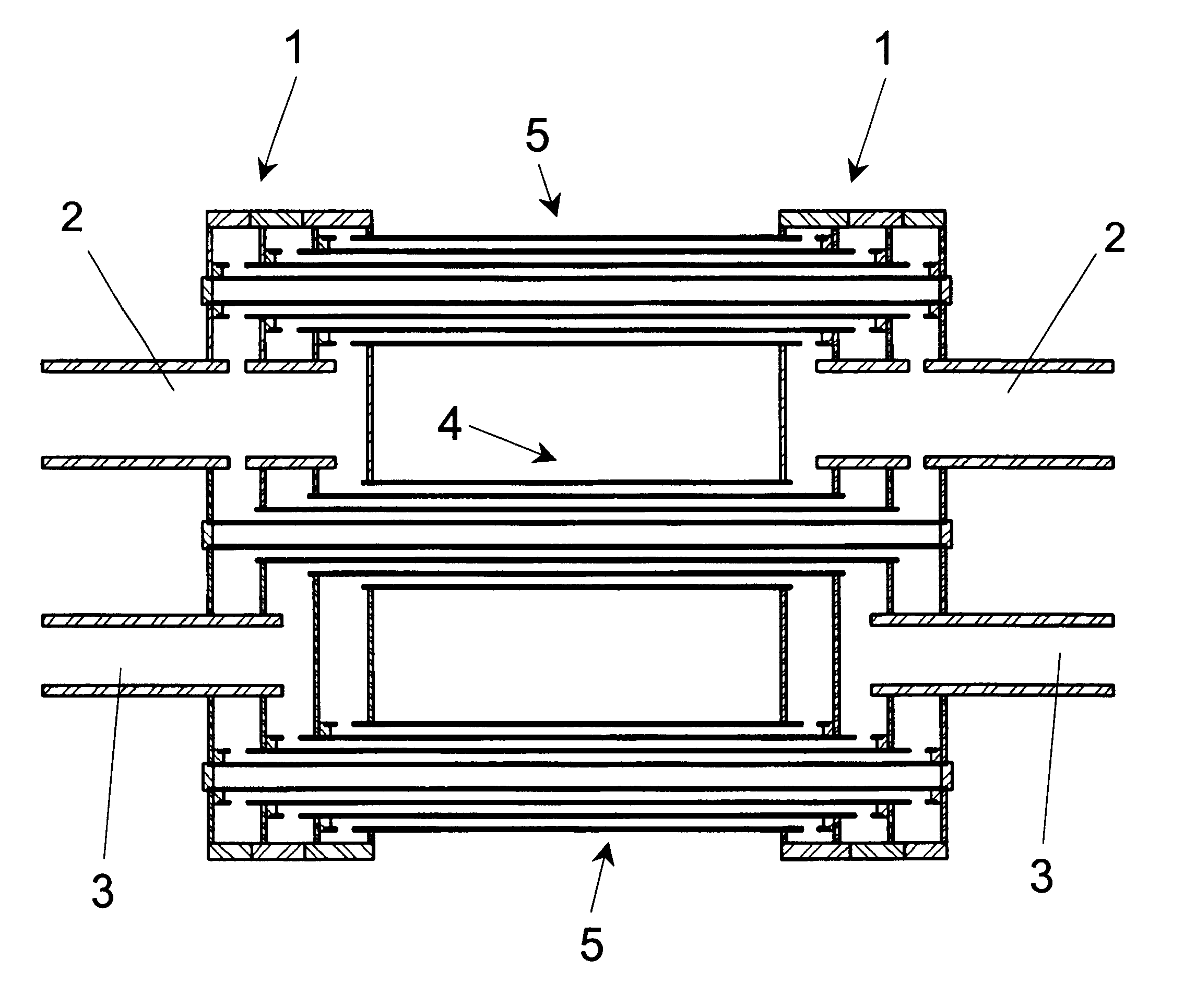
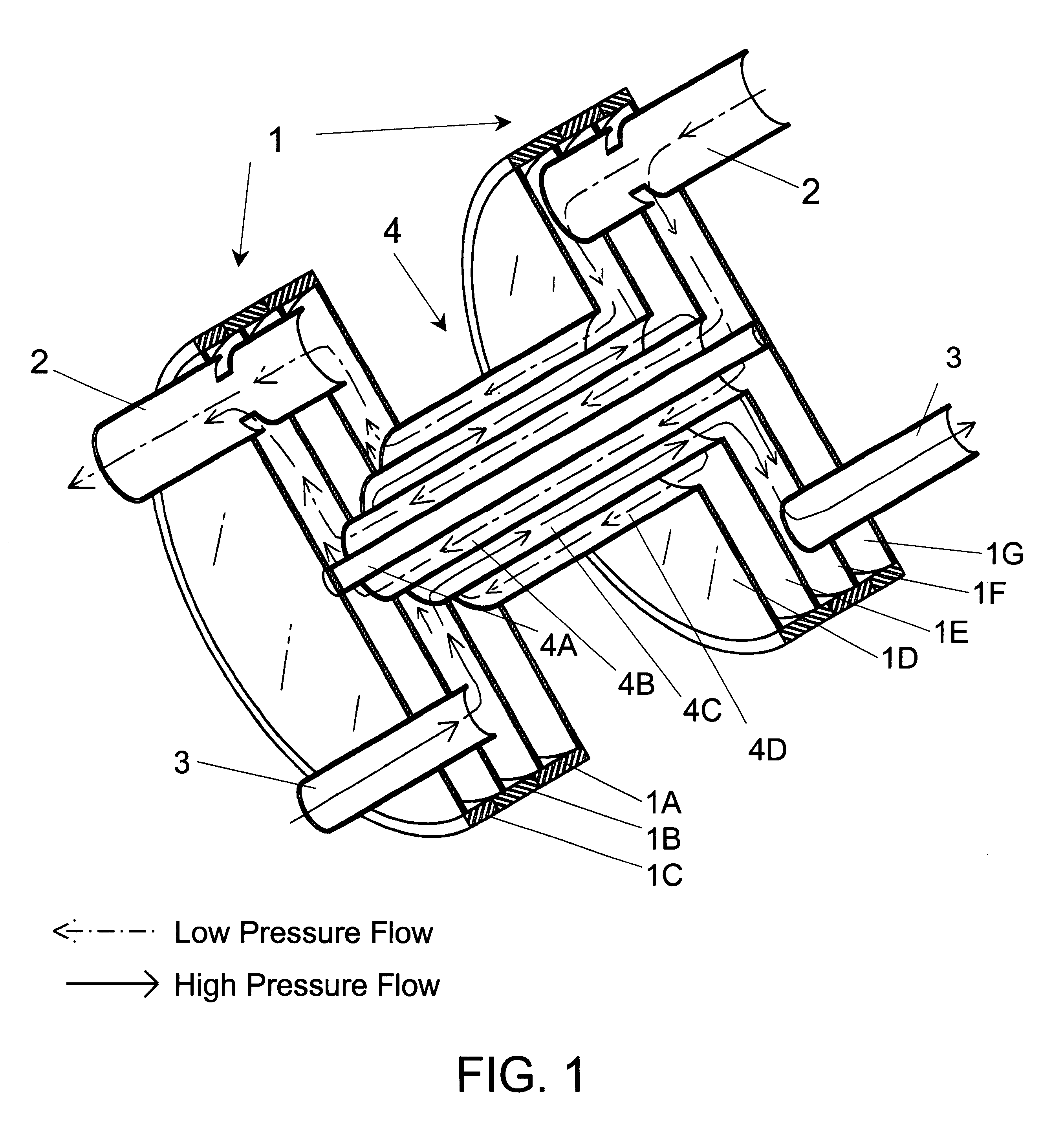
The basic components of the annular flow concentric tube recuperator are shown in the simplified cross-section of FIG. 1. The recuperator consists of two substantially identical header assemblies 1, two substantially identical low pressure flow tubes 2, two substantially identical high pressure flow tubes 3, and multiple concentric tube assemblies 4, of which, for drawing simplicity, only one is shown in FIG. 1. In the preferred embodiment, the concentric tube assemblies 4 are comprised of four tubes 4A, 4B, 4C and 4D that form the boundaries for three concentric annular flow paths. As the coded arrows show, the inner and outer flow paths are used for the low pressure flow and the high pressure flow path lies between the low pressure paths. The header assemblies 1, are each made from three tubular rings 1A, 1B, 1C and four circular plates 1D, 1E, 1F, and 1G. The rings and plates form cylindrical manifold regions to distribute the flow from the high and low pressure flow tubes 2 and ...


PUM


Abstract

An annular flow concentric tube heat exchanger for heating two counter flowing fluid streams has been devised. Although capable of heating gases or liquids, the primary purpose of the invention is to function as an improved recuperator for recovering exhaust heat from a Brayton Cycle gas turbine engine, Ericsson Cycle engine or similar recuperated engine. The basic element of the recuperator is a concentric tube assembly that, in the preferred embodiment, is comprised of four concentric tubes that enclose three concentric annular flow passages. The low pressure exhaust flows through the inner and outer annular passages while the high pressure compressor exit air flows through the annular passage that is between the two low pressure passages. The high and low pressure flows are in opposite directions to achieve the high effectiveness that is only available with a counterflow heat exchanger. Heat is transferred from the exhaust gas to the compressor air though the tube walls on each side of the high pressure passage. Two low pressure passages are provided for each high pressure air passage to compensate for the lower pressure (and therefore lower density) of the exhaust gas. Multiple concentric tube assemblies are used to make a recuperator. The tube assemblies terminate in header assemblies located at each end of the concentric tube assemblies. The headers are made of simple plates and rings that serve the dual function of structurally locating the concentric tube assemblies and directing the flow to the proper passage in the concentric tube assemblies. High and low pressure flow tubes provide flow passages connecting the recuperator to the engine compressor air and exhaust tubing respectively. The annular flow concentric tube recuperator can be easily made from commercial tubing with minimal special tooling and is capable of very high effectiveness with very low pressure drop.

Description

1. Field of the InventionThis invention relates in general to concentric tube heat exchangers. More particularly, it relates to an improved recuperator for recovering exhaust heat from a Brayton Cycle gas turbine engine, Ericsson Cycle engine, or similar recuperated engine.2. Description of Prior ArtThe thermodynamic efficiency and resulting fuel economy of a gas turbine (Brayton Cycle) engine can be greatly increased by using an exhaust gas heat exchanger to recover heat from the low pressure exhaust stream to preheat the high pressure air between the compressor and combustor. The heat thus recovered in the preheating process, which would otherwise be wasted in the exhaust, does not have to be supplied by the combustor. As a result, the cycle efficiency is typically doubled from about 15% without a heat exchanger to 30% with a heat exchanger. Newer types of engines, such as the Afterburning Ericsson Cycle of my U.S. Pat. No. 5,894,729 (1999), make even better use of an exhaust gas ...

Claims


Application Information

Patent Timeline
Patent Type & Authority Patents(United States)
IPC IPC(8): F28D7/10
CPCF28D7/103F28D21/0003
Inventor PROESCHEL, RICHARD A.
Owner PROE POWER SYST
Why Eureka
Try Eureka