
Automatic pupillometer with visual verification

a pupillometer and automatic technology, applied in the field of automatic pupillometer with visual verification, can solve the problems of affecting the measurement accuracy of the pupillometer

Active Publication Date: 2011-07-12
ESSILOR INT CIE GEN DOPTIQUE
View PDF3 Cites 7 Cited by
  • Summary
  • Abstract
  • Description
  • Claims
  • Application Information

AI Technical Summary

Benefits of technology

The invention solves the problem of verifying the proper positioning of an individual's eyes in an automatic pupillometer. This is achieved by an automatic pupillometer that includes a light source, collimator lens, detection receiver, and calculator. Additionally, the pupillometer includes a third window for the observer to verify the measurement conditions. The invention also includes actuator means for the observer to validate the measurement. The detection receiver may be a camera, and the pupillometer may include a monocular occultation arrangement with electrically-controlled diaphragms. The calculator may include modules for calculating the pupillary distance, radius of the eye, and correcting the measurement based on the distance of the eyes from the eyeglass lenses. The light source may be an infrared source, and the pupillometer may also include a light source for near vision measurement.

Problems solved by technology

That type of manual pupillometer takes time and raises problems with measurement accuracy.
That type of pupillometer, which is particularly accurate since it is independent of an operator, nevertheless raises the following problems.
The individual whose pupillary distance is to be measured may behave in a way that impedes good measurement.
This can lead to a wrong measurement of the pupillary half-distance, or indeed to a wrong measurement of the pupillary distance, if the individual is not looking at infinity.
In addition, ambient lighting conditions may disturb the measurement, thereby giving rise to inaccurate values.
In an automatic pupillometer, it is presently not possible to detect such an error.
Nevertheless, it is not always easy to verify that the eyes are open, since it can happen for example that a corneal reflection is partially visible, with the photograph being taken at an instant when the eyelid is moving, thus leading to a result being obtained that is approximate in terms of accuracy, but that cannot be said to be wrong.
Such components are generally quite expensive, bulky, and they consume large amounts of electrical energy, thus raising difficulties for an appliance that is portable.

Method used


Image

  • Automatic pupillometer with visual verification
  • Automatic pupillometer with visual verification
  • Automatic pupillometer with visual verification

Examples


Embodiment Construction

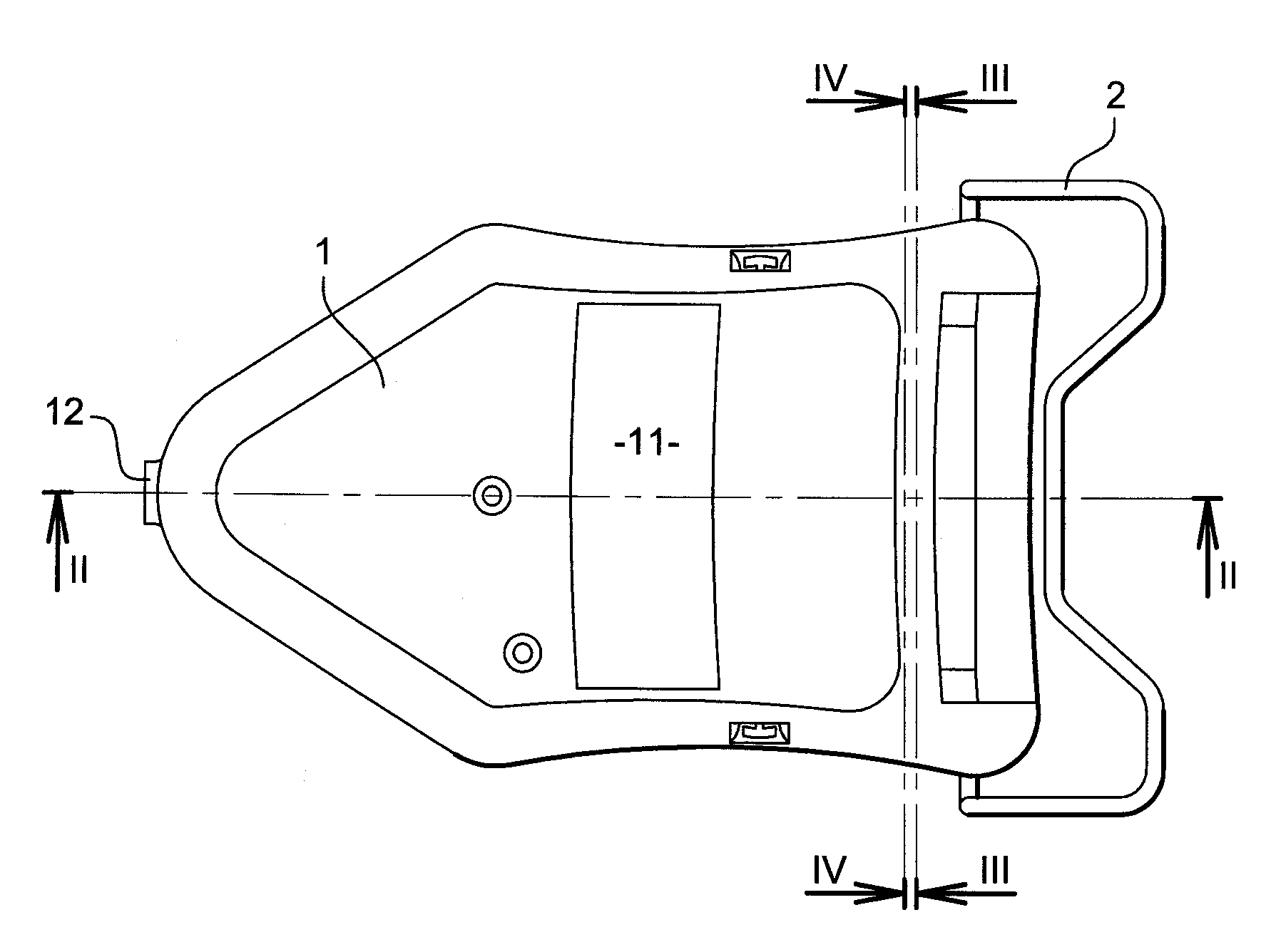
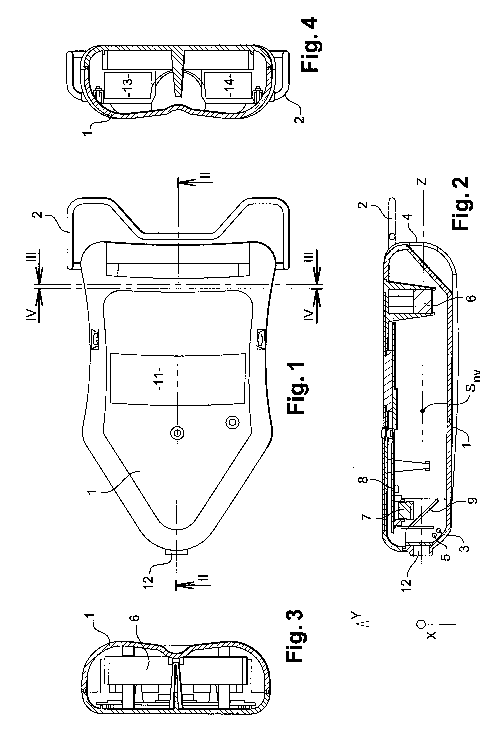
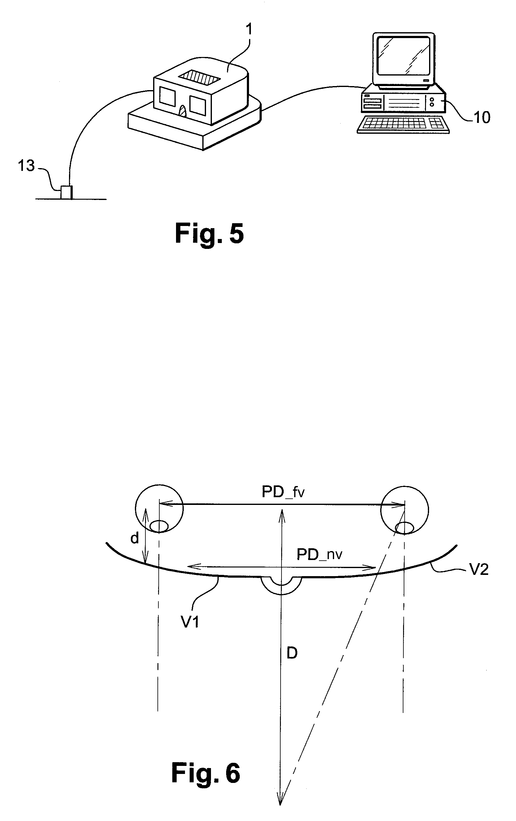
[0037]An automatic pupillometer in accordance with the invention is shown in detail in FIGS. 1 to 4.

[0038]The pupillometer comprises a housing 1 provided with a portion 2 reproducing an eyeglass frame for placing on the nose of an individual whose pupillary distance is to be measured.

[0039]Inside the housing, the automatic pupillometer comprises:[0040]an infrared light source 3 suitable for generating a corneal reflection on at least one of the eyes of the individual, each of which eyes faces a respective first or second window 4;[0041]a visible light source 5 placed beside the infrared light source and serving to be looked at and sighted by the individual;[0042]a collimator lens 6 serving at least to position the light source 3, 5 so as to correspond to far vision of the individual, the infrared light source 3 and the visible light source 5 being located in the vicinity of the focus of the lens 6;[0043]a detection receiver, constituted by a camera 7 for automatically locating said ...


PUM


Abstract

The invention relates to an automatic pupillometer comprising a light source suitable for generating a corneal reflection on at least one of the eyes of an individual facing first and second windows, a collimator lens serving at least to position the light source to correspond to far vision of the individual, a detection receiver for automatically locating said reflection, and a calculator for calculating the pupillary distance of said individual. According to the invention, the pupillometer also comprises a third window where the eye of an observer responsible for the measurement is designed to be placed in the vicinity of the focus of said lens so as to view and verify measurement conditions.

Description

Related Applications:[0001]This application is a National Phase Application of PCT / FR2008 / 051766, filed on Oct. 1, 2008, which in turn claims the benefit of priority from French Patent Application No. 07 58167, filed on Oct. 9, 2007, the entirety of which are incorporated herein by reference.BACKGROUND OF THE INVENTION[0002]1. Field of the Invention[0003]The invention relates to an automatic pupillometer with visual verification.[0004]A pupillometer is an appliance designed to measure the pupillary distance of an individual. It consists in using a light source suitable for generating a corneal reflection on at least one of the eyes of the individual, and in proceeding to locate said reflection.[0005]2. Description of the Related Art[0006]Such a pupillometer may be manual, e.g. as described in patent document FR 1 506 352.[0007]The appliance is then provided with three windows, two windows reproducing the eyeglass frame that is to be placed on the nose of the individual, and an oppos...

Claims


Application Information

Patent Timeline
Patent Type & Authority Patents(United States)
IPC IPC(8): A61B3/10
CPCA61B3/111
Inventor NAUCHE, MICHEL
Owner ESSILOR INT CIE GEN DOPTIQUE
Learn More