Vehicle control apparatus and vehicle equipped with the control apparatus

a technology of vehicle control and control apparatus, which is applied in the direction of machine/engine, vehicle sub-unit features, braking systems, etc., can solve the problems of increasing the torque ratio, deteriorating the acceleration response characteristics, and unattainable acceleration requested by the driver, so as to increase the amount of energy regenerated, and reduce the braking shock

Inactive Publication Date: 2011-07-12
HITACHI LTD
View PDF13 Cites 15 Cited by
  • Summary
  • Abstract
  • Description
  • Claims
  • Application Information

AI Technical Summary

Benefits of technology

[0006]Solving this problem requires shifting gears during regenerative braking as well. Shifting gears during regenerative braking, however, causes such a trade-off problem between the amount of energy regenerated and the magnitude of a braking shock that whereas maximizing the amount of energy regenerated augments the braking shock to its maximum, minimizing the braking shock minimizes the amount of energy regenerated.
[0009]In particular, using a larger motor correspondingly increases the regenerative torque, thus causing the above problems to easily occur.
[0010]An object of the present invention is to provide: a vehicle control apparatus adapted to increase the amount of energy regenerated, as well as to reduce braking shocks, during downshift control for deceleration; and a motor vehicle equipped with the control apparatus.
[0011](1) In order to achieve the above object, the present invention provides, as an aspect thereof, a vehicle control apparatus for a motor vehicle which includes wheels, a motor, a brake, and a multi-stage transmission, and which is designed to transmit a torque of the motor to the wheels via the multi-stage transmission. This vehicle control apparatus adapted to control a braking force of the vehicle by using a braking torque of the motor and a braking force of the brake comprises gear shift control means that performs a gear shift of the multi-stage transmission according to a particular state of the vehicle, and torque distribution control means that controls distribution of the braking torques of the motor and the brake. This construction allows the vehicle control apparatus to reduce a braking shock when controlling a downshift for deceleration, and to increase the amount of energy regenerated during the control of the downshift.
[0023]This construction allows the vehicle control apparatus to reduce a braking shock when controlling a downshift for deceleration, and to increase the amount of energy regenerated during the control of the downshift.
[0024]According to the present invention, during downshift control for deceleration, braking shocks can be reduced and the amount of energy regenerated can be increased.

Problems solved by technology

As described in JP-A-10-73161, however, the inhibition of the downshift means that after the vehicle has slowed down to a certain degree, when the driver changes the position of the foot from the brake pedal to the accelerator pedal, the acceleration requested by the driver will be unattainable since the high-speed gear position that has been used up until the start of the slowdown will still be maintained.
To accelerate the vehicle, therefore, the driver will need first to perform a downshift, which will deteriorate acceleration response characteristics.
Shifting gears during regenerative braking, however, causes such a trade-off problem between the amount of energy regenerated and the magnitude of a braking shock that whereas maximizing the amount of energy regenerated augments the braking shock to its maximum, minimizing the braking shock minimizes the amount of energy regenerated.
In the torque phase, an increase in the torque ratio causes a braking shock.
Meanwhile, as described in JP-A-2006-151018, reducing a regenerative torque for minimum braking shock causes the problems that the energy needed to compensate for an increase in the torque ratio and for the inertia torque is not regenerated and hence that the amount of regeneration obtained will naturally decrease.

Method used


Image

  • Vehicle control apparatus and vehicle equipped with the control apparatus
  • Vehicle control apparatus and vehicle equipped with the control apparatus
  • Vehicle control apparatus and vehicle equipped with the control apparatus

Examples


Embodiment Construction

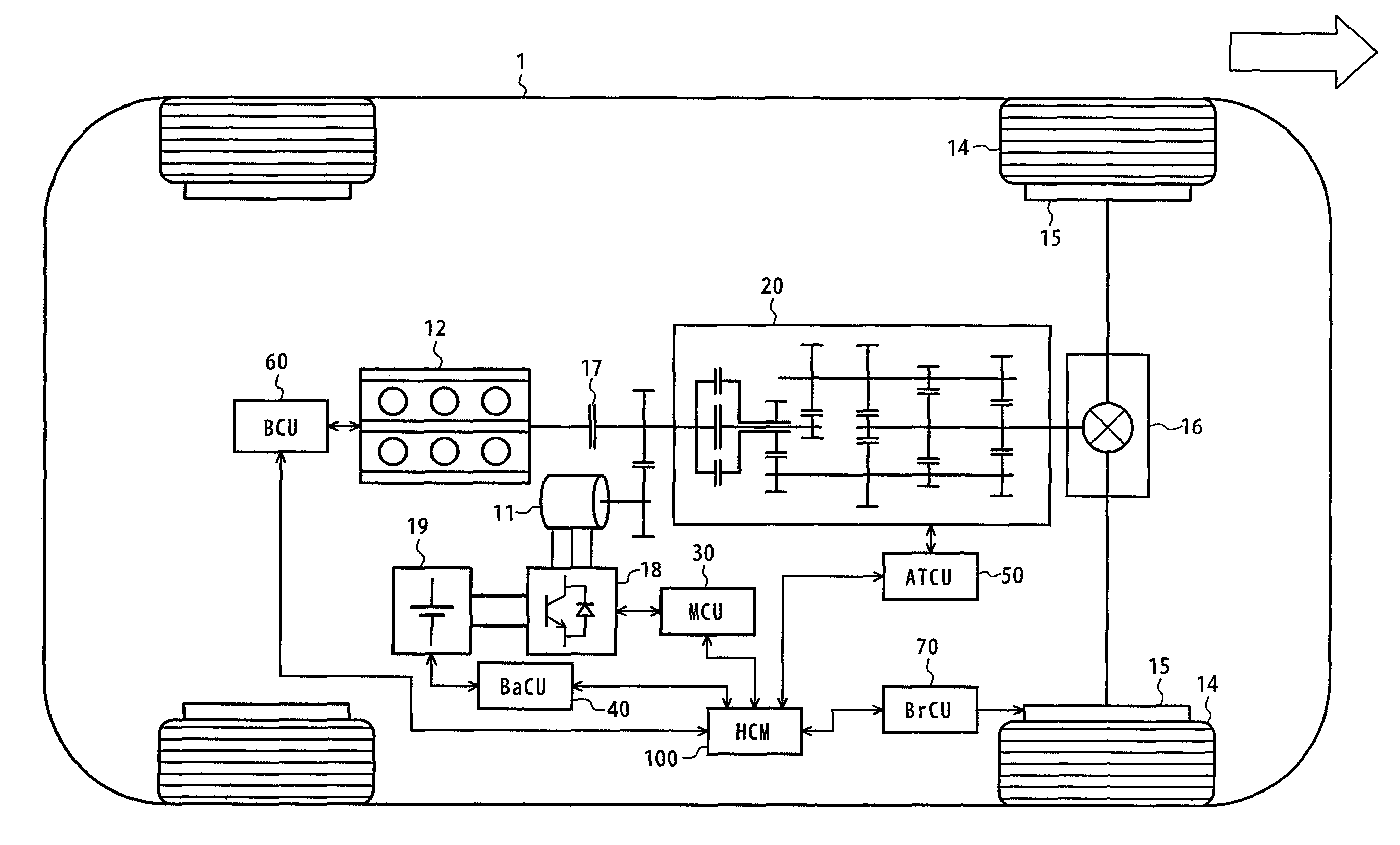
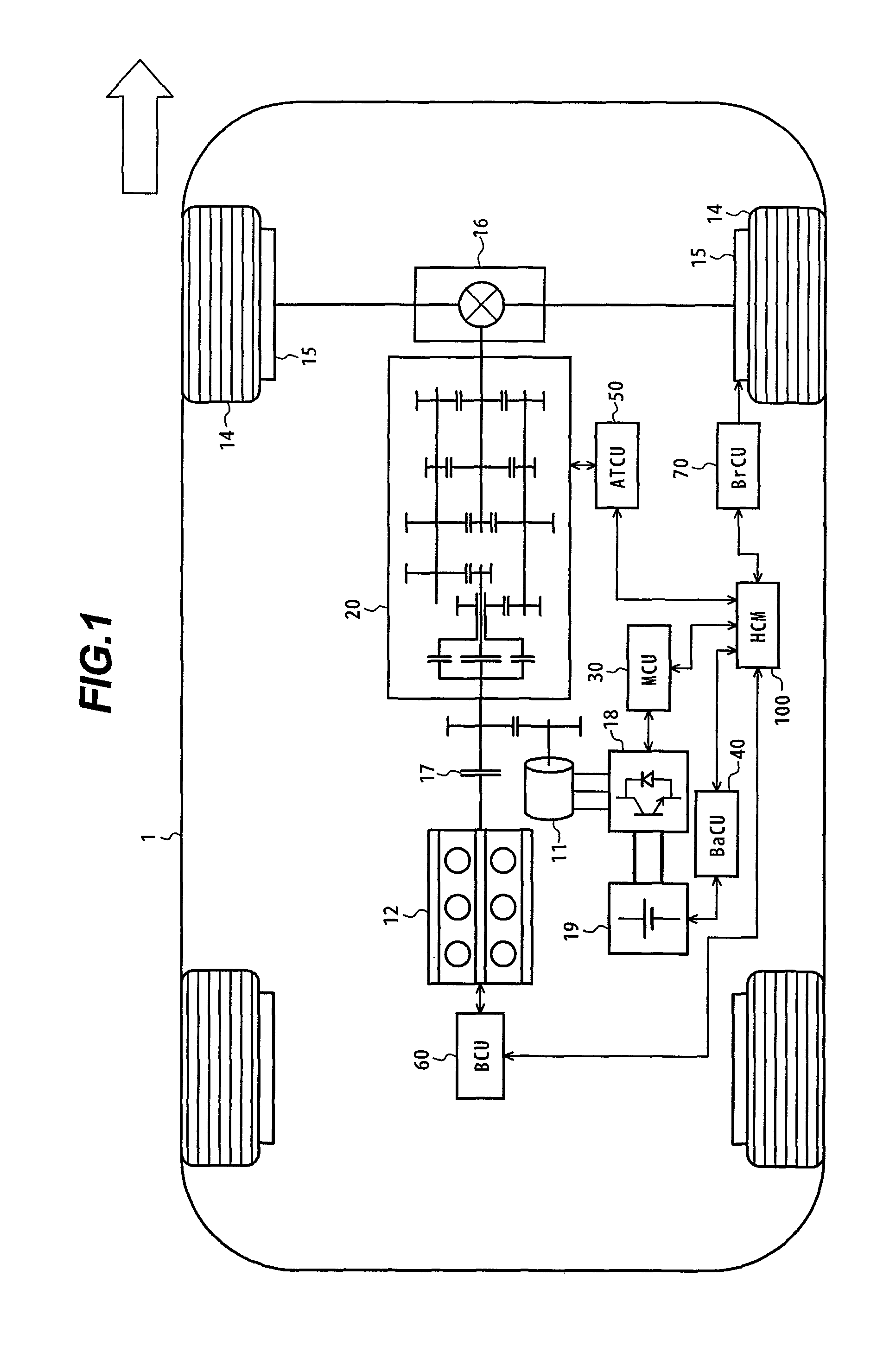
[0042]Hereunder, a configuration and operation of a vehicle control apparatus according to an embodiment of the present invention will be described using FIGS. 1 to 17. A configuration of hybrid vehicle with the vehicle control apparatus according to the present embodiment is first described using FIG. 1.

[0043]FIG. 1 is a system block diagram showing the configuration of the hybrid vehicle equipped with the vehicle control apparatus according to the present embodiment.

[0044]The hybrid vehicle 1 has a motor 11 as a braking and driving source. The motor 11 is a three-phase AC synchronous motor, for example. The motor 11 can generate a braking force and a driving force by exchanging electrical energy with a battery 19 via an inverter 18. The synchronous motor can be replaced by any other motor such as an induction motor or a DC motor with brushes.

[0045]A motor control apparatus (MCU) 30 controls a driving torque of the motor 11 by controlling the inverter 18 and making variable an arma...


PUM


Abstract

This invention provides a vehicle control apparatus constructed so that during the control of a downshift for deceleration, braking shocks can be reduced and the amount of energy regenerated can be increased, and a hybrid vehicle equipped with the control apparatus.The hybrid vehicle 1 includes wheels 14, an engine 12, a motor 11, a multi-stage transmission 20 that reduces motor torque and transmits the reduced torque to the wheels, and a brake 15 that brakes the wheels. During deceleration downshift control, a hybrid control module 100 provides distribution control of the regenerative torque of the motor 11 and the braking torque of the brake 15 so that the total braking force of the vehicle during gear shifting matches a target value.

Description

BACKGROUND OF THE INVENTION[0001]1. Field of the Invention[0002]The present invention relates generally to vehicle control apparatus and to motor vehicles equipped with a vehicle control apparatus. More particularly, the invention concerns a vehicle control apparatus suitable for downshift control during deceleration of a motor vehicle including a motor and a brake as braking sources for the vehicle and using a multi-stage transmission on a torque-transmitting route of the motor.[0003]2. Description of the Related Art[0004]A technique for inhibiting a downshift during deceleration in order to raise energy-regenerating efficiency is known as a method of controlling a downshift during deceleration of a hybrid automobile equipped with a multi-stage transmission. JP-A-10-73161, for example, describes such a technique. Also known is a technique intended to prevent the occurrence of a driving force during the downshift of a vehicle by controlling the total of a motor regenerative torque a...

Claims


Application Information

Patent Timeline
Patent Type & Authority Patents(United States)
IPC IPC(8): B60W10/08B60K6/48B60K6/547B60T8/17B60W10/04B60W10/10B60W10/18B60W10/188B60W10/192B60W20/00F02D29/00F02D29/02
CPCB60K6/48B60W10/02B60W10/06B60W10/08B60W10/113B60W30/18109B60W30/18136B60W30/19B60K6/547Y10T477/69367B60L2240/423B60L2240/441B60L2240/443B60L2240/486B60W20/00B60W2510/0275B60W2510/0638B60W2510/0657B60W2510/1015B60W2510/1025B60W2710/027B60W2710/0666B60W2710/083B60W2710/1022B60W2710/105B60Y2400/428Y02T10/6221Y02T10/6286Y02T10/642Y10T477/24Y10T477/677Y02T10/62Y02T10/64B60W10/18B60W10/10
Inventor YAMAMOTO, DAISUKETAKAKU, YUTAKA
Owner HITACHI LTD
Why Eureka
Try Eureka