Haemostasis device

a technology of haemostasis and connector, which is applied in the direction of intravenous devices, catheters, other medical devices, etc., can solve the problems of patient blood loss, difficult to achieve adequate sealing properties, cumbersome and time-consuming use by clinicians, etc., and achieves the effect of easy gripping of the connector member and easy gripping by users

Active Publication Date: 2011-07-12
TELEFLEX LIFE SCI LTD
View PDF30 Cites 16 Cited by
  • Summary
  • Abstract
  • Description
  • Claims
  • Application Information

AI Technical Summary

Benefits of technology

[0009]The tubular member provides a simple, visual means of indicating to the user whether the low pressure seal is in the closed configuration or in the open configuration. The user can therefore avoid blood loss through a partially open seal, and can avoid attempting to pass a medical device, such as a stent, through a partially open seal.
[0080]The haemostasis device of the invention provides a simple, easy-to-use mechanism, whereby open / close positions are readily recognisable. This substantially reduces the risk of stents getting damaged inadvertently through seals being half-open. It is ideally suited to the delivery of fragile loads on balloon catheters or stent-delivery systems, such as drug-eluting stents, in particular through the avoidance of any seal contact. Moreover, correct use of the sealing mechanism can lead to a significant reduction in blood loss. As well as saving time through the avoidance of wearisome threading / re-threading of valves, it also affords improved ergonomics for the user by the design of the enhanced cap and the addition of finger rests.

Problems solved by technology

They can be cumbersome and time-consuming to use by a clinician.
Some devices require manual threading of caps, and it can be difficult to effect adequate sealing properties.
If valves are left open or partially open, this can lead to patient blood loss through seal leakage, with consequent reduced blood pressure.
If users are unclear about the valves being open, half-open or closed, this can lead to expensive stents getting damaged by being pulled through half-open seals.

Method used


Image

  • Haemostasis device
  • Haemostasis device
  • Haemostasis device

Examples


Embodiment Construction

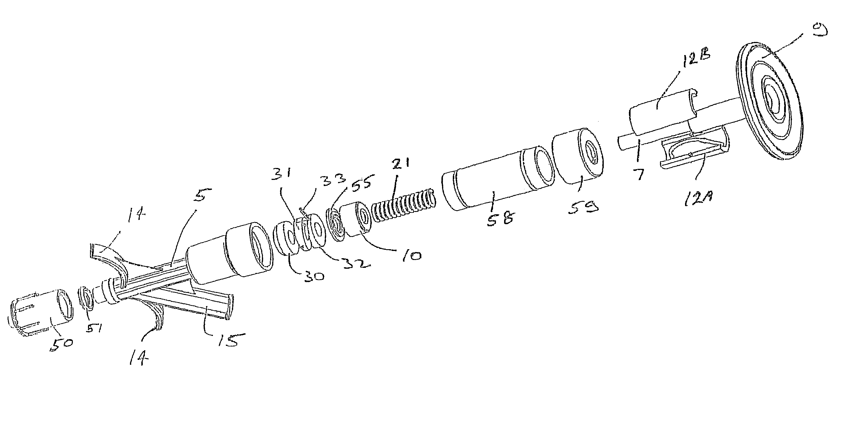
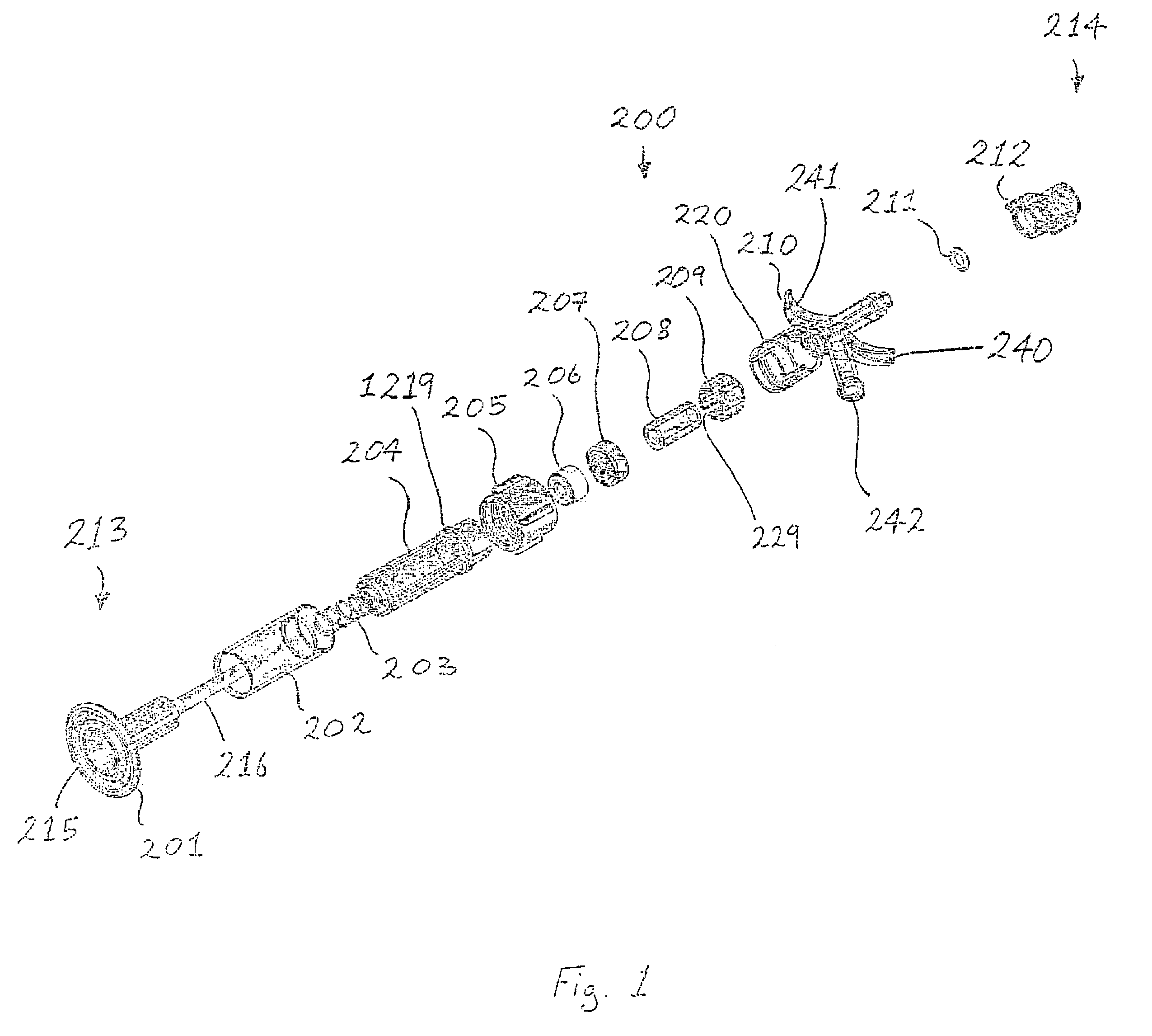
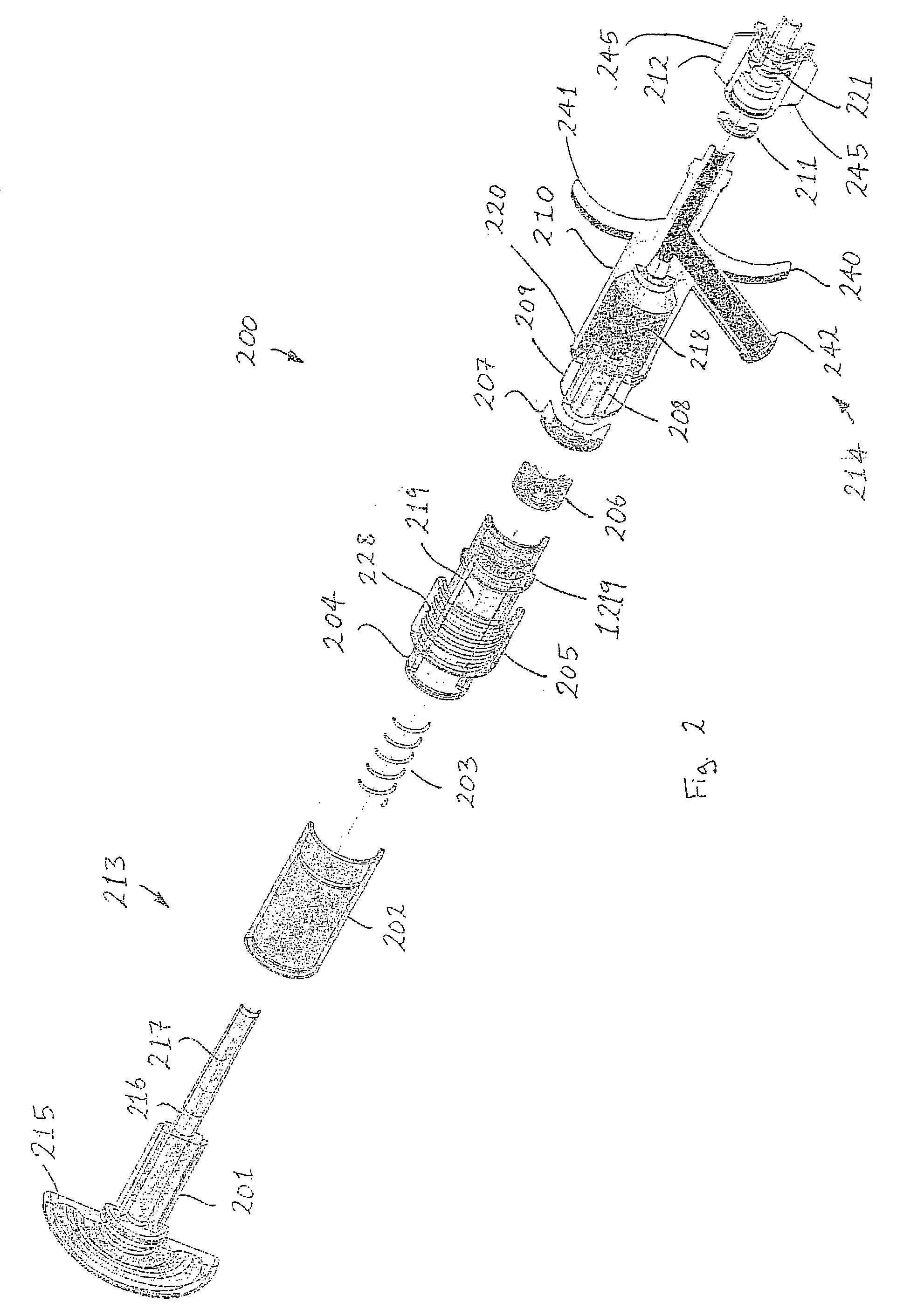
[0131]Referring to FIGS. 1 to 39, there is illustrated a haemostasis device 200 according to the invention. The device 200 is a rotating haemostasis valve and comprises two sealing mechanisms. The device 200 is constructed using injection moulded plastic. Each sealing mechanism has an elastomeric component which is actuated to perform an “opening” or “closing” action.

[0132]As illustrated in FIGS. 1 and 2, moving from the proximal end 213 to the distal end 214, the device 200 comprises:[0133]a bayonet 201;[0134]a skirt 202;[0135]a coiled spring 203;[0136]an upper body housing 204;[0137]a roto-lock nut 205;[0138]a low pressure seal 206;[0139]a spacer 207;[0140]a high pressure seal 208;[0141]a collet 209;[0142]a lower main body portion 210;[0143]an O-ring 211; and[0144]a luer 212.

[0145]The bayonet 201 comprises a proximal end cap 215 and a tubular plunger member 216 extending distally from the end cap 215. A lumen 217 extends through the bayonet 201.

[0146]The tubular member 216 support...


PUM


Abstract

A haemostasis device (200) comprises a low pressure seal (206) and a high pressure seal (208). A tubular bayonet (201) is movable from a retracted configuration to an inserted configuration to move the low pressure seal (206) between a closed configuration and an open configuration. With the low pressure seal (206) in the open configuration, a guidewire (222) may be inserted through the low pressure seal (206), and with the low pressure seal (206) in the closed configuration, the guidewire (222) may be passed through the low pressure seal (206) while maintaining sealing around the guidewire (222). A collet (209) is movable in a radial direction to move the high pressure seal (208) between an open configuration and a sealing configuration. With the high pressure seal (208) in the sealing configuration, the guidewire (222) is locked in position.

Description

[0001]This is a complete application claiming benefit of provisional 60 / 497,570 filed Aug. 26, 2003.[0002]This invention relates to a haemostasis device.[0003]It is known to employ a haemostasis device for providing haemostasis while facilitating passage of a medical device, for example an elongated member, such as a guidewire or a catheter, through the haemostasis device and into a vasculature. Such a haemostasis device may be used, for example, in an interventional procedure, such as a balloon angioplasty and / or a stenting procedure.[0004]Currently available haemostasis devices have a number of disadvantages. They can be cumbersome and time-consuming to use by a clinician. Some devices require manual threading of caps, and it can be difficult to effect adequate sealing properties. If valves are left open or partially open, this can lead to patient blood loss through seal leakage, with consequent reduced blood pressure. If users are unclear about the valves being open, half-open or...

Claims


Application Information

Patent Timeline
Patent Type & Authority Patents(United States)
IPC IPC(8): A61M5/178A61M39/06
CPCA61M39/0613A61M39/0693A61M2039/062A61M2039/0673
Inventor KHAN, MAZHAR M.MULLOY, AIDANRONAN, DAVIDBRETT, GERARDMULLOY, LIAM
Owner TELEFLEX LIFE SCI LTD
Why Eureka
Try Eureka