Mechanical lock stop system and method

a technology of mechanical locks and stops, applied in the direction of loading/unloading vehicle arrangment, transportation items, load accommodation, etc., can solve the problems of loss of control, decreased safety of operators, loss of control, etc., to increase the safety of the lock stop system, simple and economical to assemble, and easy to use

Inactive Publication Date: 2011-07-19
THE BOEING CO
View PDF6 Cites 5 Cited by
  • Summary
  • Abstract
  • Description
  • Claims
  • Application Information

AI Technical Summary

Benefits of technology

[0006]This need for a mechanical lock stop system and method that provides advantages over known systems and methods is satisfied. Unlike known systems and methods, embodiments of the mechanical lock stop system and method of the disclosure may provide one or more of the following advantages: provides a mechanical lock stop system and method that locks and positions a load in place on a device such as a movable mechanical articulating device; provides a mechanical lock stop system and method that stops and locks a load in place automatically if such load slips for any reason and creates a solid positive mechanical lock wherever an operator deems necessary; provides a mechanical lock stop system and method that may be used for any application that requires moving equipment that moves on a linear bearing and an extruded part that has pressure or weight against it and that requires a safety lock or position lock; provides a mechanical lock stop system and method that in the event of an accidental loss of control of the load is stopped and locked in the closest increment or periodic location on the length of a modular extruded part, thus increasing the safety of the lock stop system; provides a mechanical lock stop system and method that is easy to use and does not require manual tightening of a lock; provides a mechanical lock stop system and method that is simple and economical to assemble; provides a mechanical lock stop system and method that is ergonomically advantageous by making the load easier to lift, easier to control, and easier to lock in place, and no longer requires the load to be lifted in free space which can result in loss of control; provides a mechanical lock stop system and method that stops the linear motion of the device on which it is installed and allows an operator to release a linear bearing for normal movement by means of depressing a push release element; and, provides a mechanical lock stop system and method for locking a load in place such as a load used to assemble aircraft, spacecraft, vehicles, buildings, and other suitable objects.

Problems solved by technology

However, such manual moving and installation lacks ease of use and can result in loss of control and decreased safety if an operator lets go of the load for any reason.
However, when the rigid barrier panel moves along the extruded part from a sloped position to a vertical position or vice versa, there is the possibility that the rigid barrier panel may slip or fall, thus resulting in loss of control.
However, if there is a slip of any kind which causes the rigid barrier panel to be released, loss of control results which can make it difficult or impossible for an operator to reach up and twist the handle to lock the rigid barrier panel back in place Moreover, known friction locks lack ease of use due to the need to manually tighten the lock handle to adjust the friction.
If the friction is not adjusted tightly enough, unwanted movement of the rigid barrier panel can occur.
Also, known friction locks are not positive mechanical locks and may be overridden.

Method used


Image

  • Mechanical lock stop system and method
  • Mechanical lock stop system and method
  • Mechanical lock stop system and method

Examples


Embodiment Construction

[0033]Disclosed embodiments will now be described more fully hereinafter with reference to the accompanying drawings, in which some, but not all of the disclosed embodiments are shown. Indeed, several different embodiments may be provided and should not be construed as limited to the embodiments set forth herein. Rather, these embodiments are provided so that this disclosure will be thorough and complete and will fully convey the scope of the disclosure to those skilled in the art.

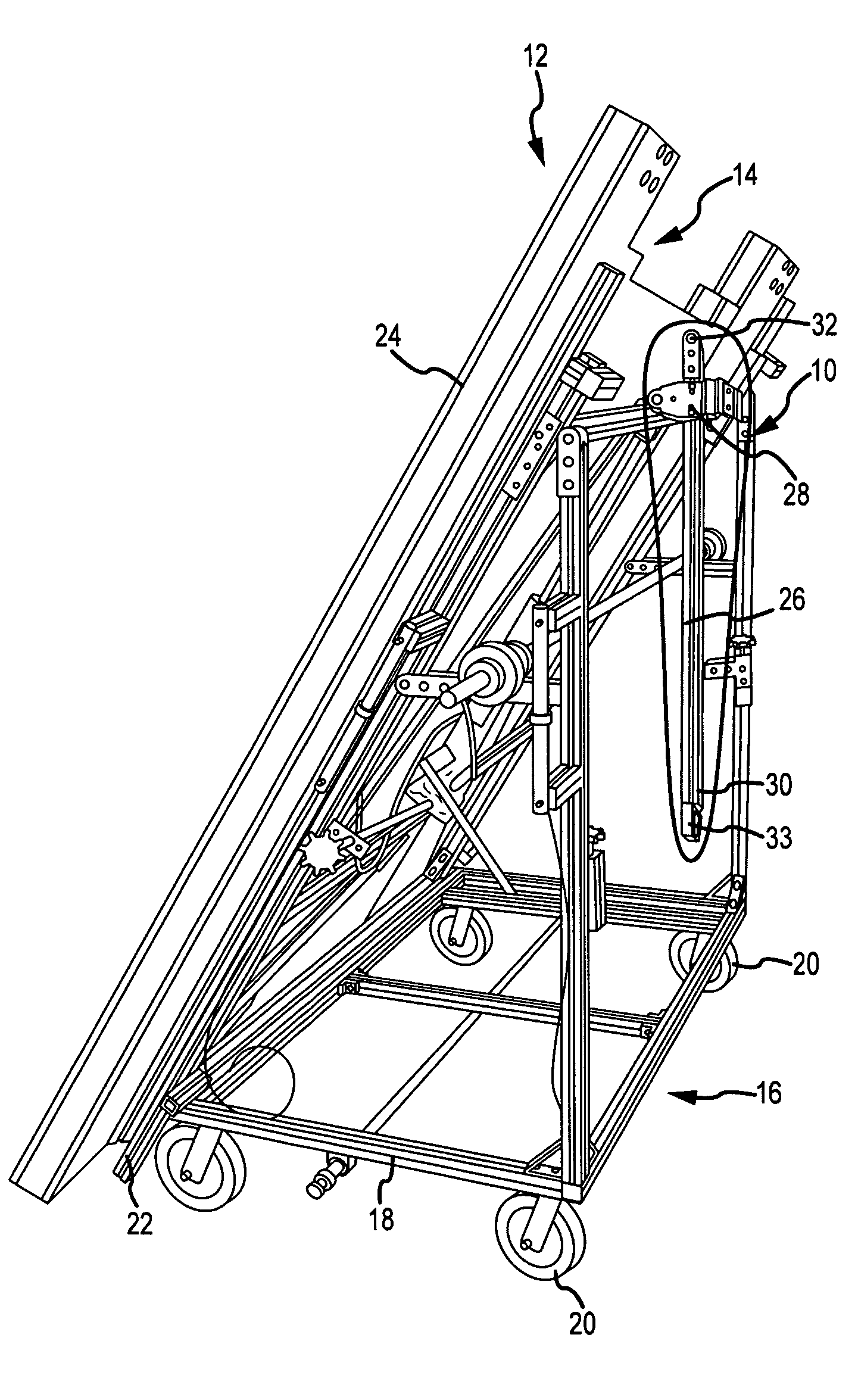
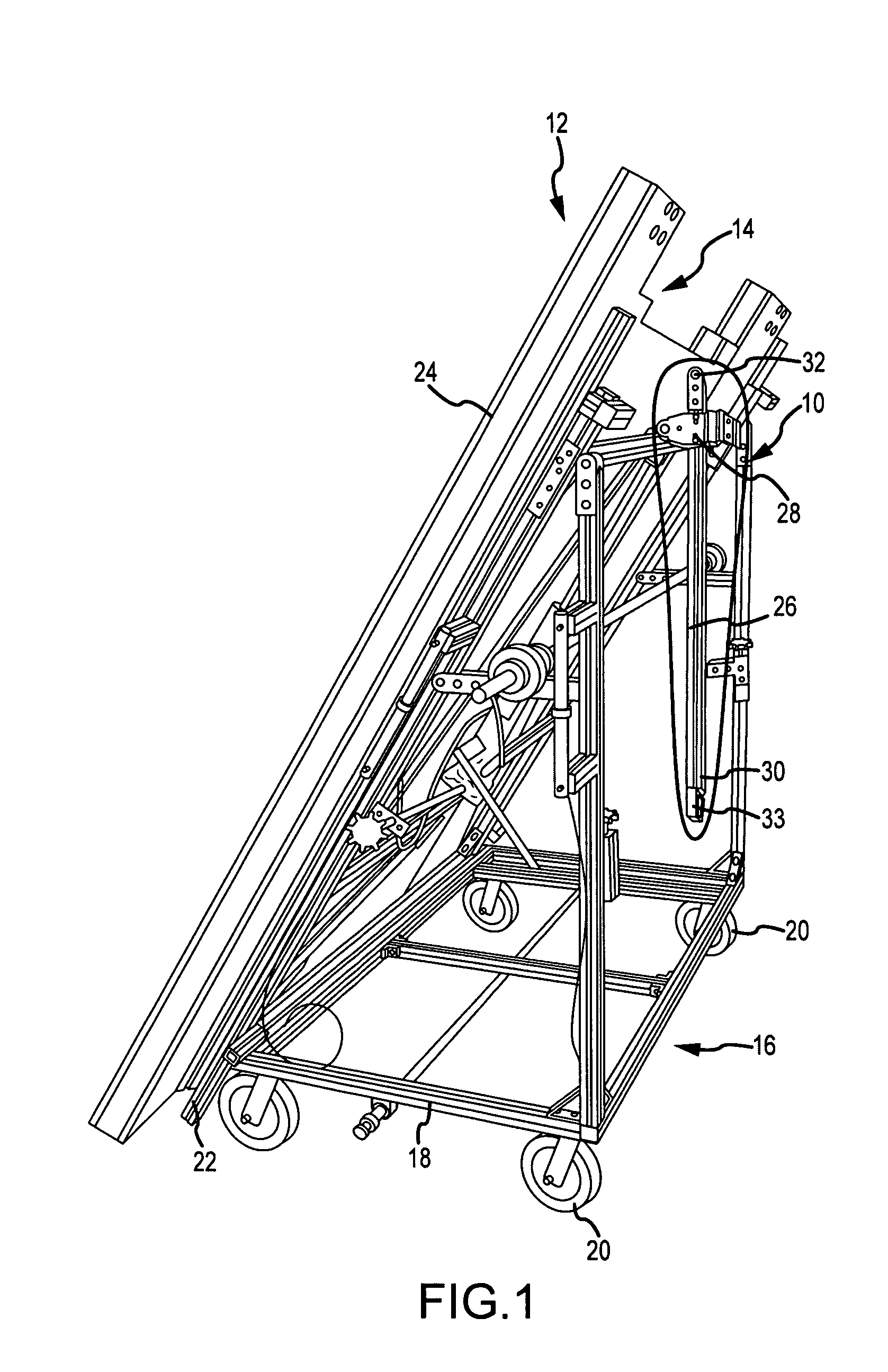
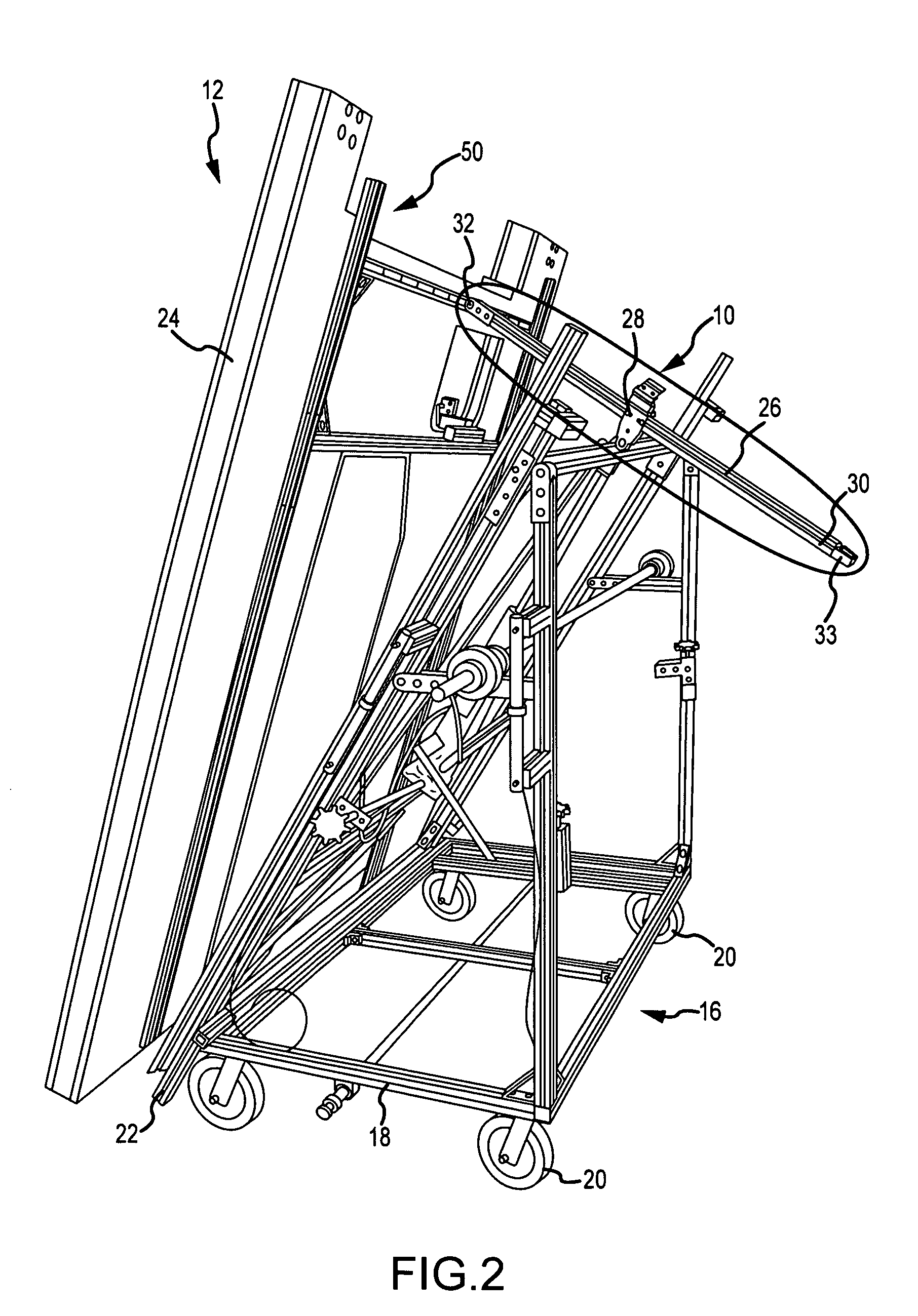
[0034]The disclosure provides for embodiments of a mechanical lock stop system and method. The mechanical lock stop system and method may be used for locking a load in place such as a load used to assemble aircraft, spacecraft, vehicles, buildings, and other suitable objects. Accordingly, one of ordinary skill in the art will recognize and appreciate that the system and method of the disclosure can be used in any number of applications involving locking loads in place such as loads used to assemble aircraf...


PUM


Abstract

The disclosure provides for a lock stop system and method. In one embodiment there is provided a mechanical lock stop system for locking and controlled movement of a load. The system comprises a modular extruded part having a plurality of spaced openings on at least one side of the modular extruded part. The system further comprises a lock stop apparatus comprising a linear bearing having at least two sides, wherein the modular extruded part moves through the linear bearing; a release element having an attached hinge; a locking element having a first end and a second end; and a compression spring mounted around at least a portion of the locking element. The release element locks and unlocks the first end of the locking element to the modular extruded part.

Description

BACKGROUND[0001]1) Field of the Disclosure[0002]The disclosure relates to mechanical lock stop systems. In particular, the disclosure relates to a mechanical lock stop system and method for stopping the motion of a load on a device on which the system is installed.[0003]2) Description of Related Art[0004]In assembling aircraft, spacecraft, vehicles, buildings, and other objects, it is often necessary to move and install loads, such as heavy and lighter weight rigid barrier panels, for use in such assembly. Such loads may be moved and installed manually. However, such manual moving and installation lacks ease of use and can result in loss of control and decreased safety if an operator lets go of the load for any reason. In addition, loads such as a rigid barrier panel may be placed at a sloped position on a movable mechanical articulating device, such as a device having wheels, and moved to a desired location, and once the desired location is reached, the rigid barrier panel may be a...

Claims


Application Information

Patent Timeline
Patent Type & Authority Patents(United States)
IPC IPC(8): B61D3/16
CPCB64F5/0009B64F5/10
Inventor SALT, KEVIN L.
Owner THE BOEING CO
Why Eureka
Try Eureka