Energization timing determination circuit and determination method for energization timing of motor

a technology of energization timing and determination circuit, which is applied in the direction of motor/generator/converter stopper, electronic commutator, dynamo-electric converter control, etc., can solve the problems of delay in the phase of the induced voltage signal, considerable variation, and inability to use hall elements in applications involving high-temperature environments, so as to reduce processing requirements and reduce processing load

Inactive Publication Date: 2011-07-19
DENSO CORP
View PDF4 Cites 8 Cited by
  • Summary
  • Abstract
  • Description
  • Claims
  • Application Information

AI Technical Summary

Benefits of technology

[0017]In an exemplary energization timing determination circuit, a detected shift length computing means computes a shift length based on a position signal switching interval obtained from position signals outputted from a position detecting means during at least the last one cycle. The detected shift length of the position signals is thereby determined. A correcting means corrects energization timing based on the position signals according to the detected shift length. The position detecting means is required to output a position signal in any one of a variety of ways. Therefore, the position detecting means can include position detection sensors, such as Hall elements, the position detection unit 9 used in sensorless driving illustrated in FIG. 10, or other constructions as would be apparent. The above correction makes it possible to determine appropriate energization timing according to the rotational state of the motor. When the motor is driven with the determined energization timing, it is possible to reduce torque ripples to enhance the driving efficiency of the motor and further suppress abnormal noise.
[0022]A detected shift length computing means further expands or contracts a time axis on which computation is based, based on an amount of change in rotational speed and places a position signal switching time already acquired on the time axis making it possible to assume a constant speed state even when the speed of a motor varies. When a detected shift length is determined from a position signal switching interval obtained from the switching time, energization timing in actual time can be determined by correcting energization timing on the expanded or contracted time axis and transforming the result of the correction back into the original time axis.
[0023]In an exemplary energization timing determination circuit, detected shift lengths that are determined by a detected shift length computing means are stored in a storing means. When a detected shift length is stored in the storing means, a correcting means reads the detected shift length to correct energization timing. Therefore, the detected shift length computing means need not frequently carry out computation to determine a detected shift length, and a processing load can be reduced. A detected shift length computing means further determines a detected shift length at predetermined intervals and stores the detected shift length in a storing means. Therefore, a detected shift length used for correction can be updated at predetermined intervals. A detected shift length computing means further determines a detected shift length when a condition change determining means determines that the drive condition or ambient environment of a motor has changed, and stores the detected shift length in a storing means. Therefore, a detected shift length can be updated according to change in the drive condition or change in the ambient environment of the motor.
[0024]A detected shift length computed by a detected shift length computing means according to a drive condition or an ambient environment is stored beforehand in a storing means. A correcting means reads a detected shift length corresponding to the drive condition or ambient environment of a motor from the storing means to carry out correction. Therefore, it is unnecessary to carry out computation to determine a detected shift length while driving of a motor is being controlled, and processing required for correction can be reduced.

Problems solved by technology

However, disadvantages arise in that when such a construction is adopted, a wiring for supplying power to the Hall elements and a wiring for obtaining detection output are required complicating the structure of the motor.
In addition, Hall elements cannot be used in applications involving a high-temperature environment.
As a result, a delay occurs in the phases of the induced voltage signal that passes through the filter 7.
Further, due to tolerances of filters 7, CR time constants are susceptible to temperature resulting in considerable variation.
If there is a discrepancy in position detection, energization timing varies and abnormal noise or degradation in efficiency due to torque ripples results.
The above problem pertains not only to sensorless drive systems.

Method used


Image

  • Energization timing determination circuit and determination method for energization timing of motor
  • Energization timing determination circuit and determination method for energization timing of motor
  • Energization timing determination circuit and determination method for energization timing of motor

Examples


first embodiment

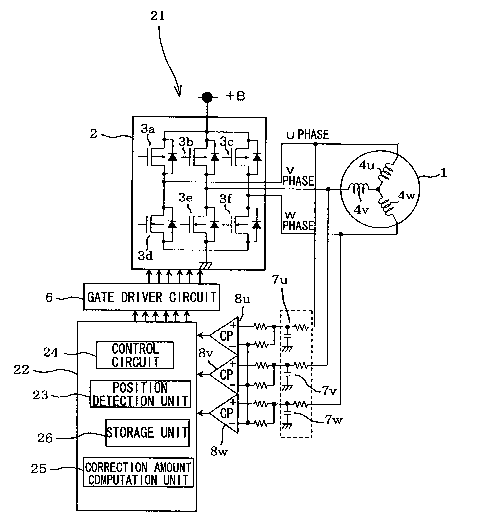
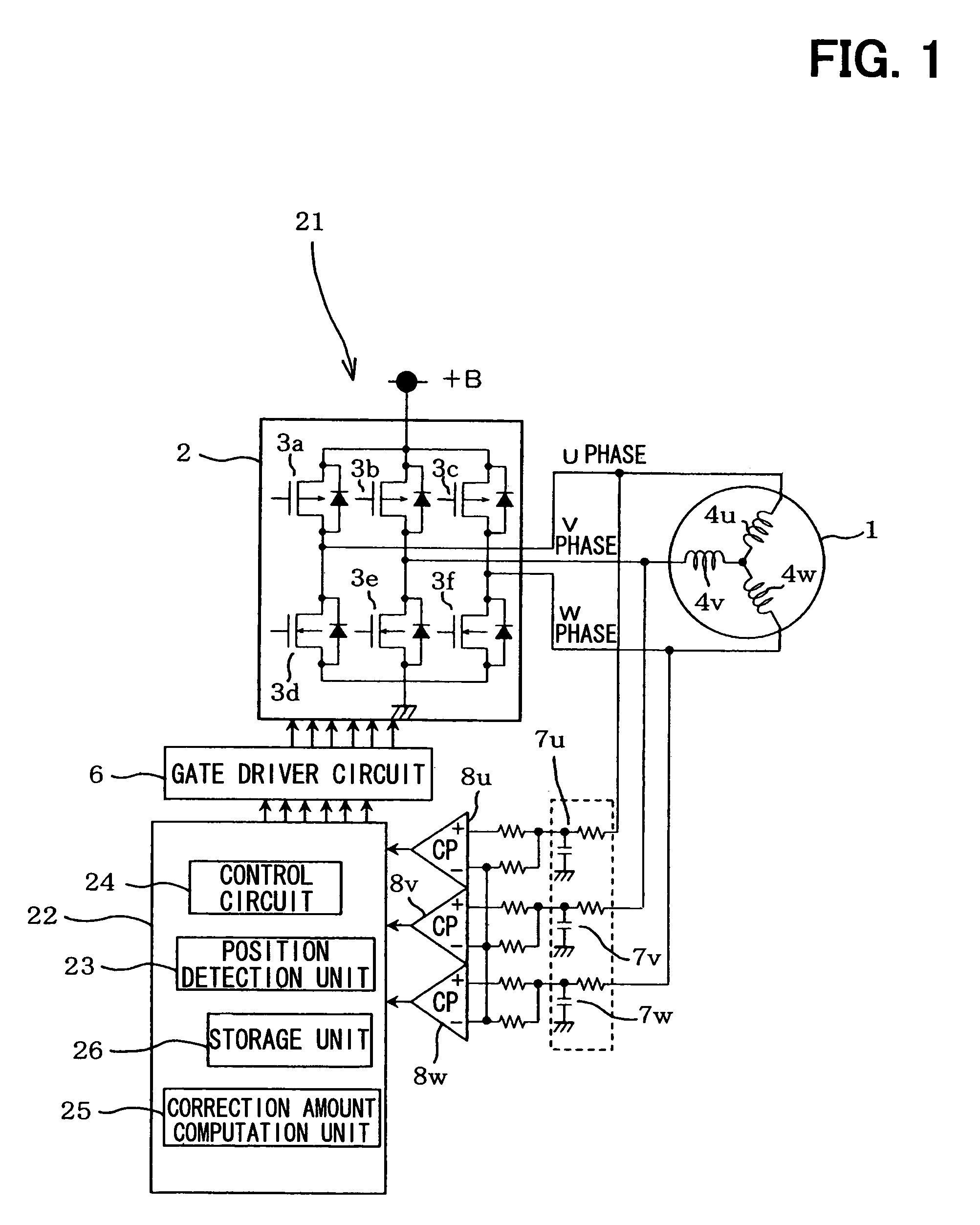
[0040]Hereafter, description will be given to a first embodiment of the invention with reference to the drawings from FIG. 1 to FIG. 4. The same members as in FIG. 10 will be marked with the same reference numerals, and the description of them will be omitted. Hereafter, description will be given to a difference. The configuration of a motor driving device 21 in this embodiment is such that the control unit 5 of the driving device 11 in FIG. 10 is replaced with a control unit 22. The control unit 22, which can operate as an energization timing determination circuit, includes a position detection unit 23, which can function as a position detecting means, a control circuit 24, which can function as a correcting means, a correction amount computation unit 25, which can function as a detected shift length computing means, and a storage unit 26 in place of a position detection unit 9 and a control circuit 10.

[0041]The correction amount computation unit 25 is a functional portion used to ...

second embodiment

[0060]FIG. 5 illustrates a second embodiment of the invention. The description of elements in common with the first embodiment that are marked with the same reference numerals is omitted for simplicity. Hereafter, description will be focused on the differences between the first and second embodiments. The construction of the second embodiment is basically the same as that of the first embodiment, except the details of processing carried out by the control unit 22. In the first embodiment, the motor 1 is assumed to be running at a constant speed, while in the second embodiments correction is carried out with the motor 1 assumed to be accelerated or decelerated.

[0061]The processing of S3 at which the latest Tx is stored in the flow illustrated in FIG. 3 is replaced with the processing in which the latest Tx is stored and at the same time, the original Tx, that is, Tx one cycle before is stored as Tx′ at S3′. At S6 in the first embodiment, it is determined whether data sufficient to co...

third embodiment

[0065]FIG. 6 illustrates a third embodiment of the invention. Description will be focused on the differences from the first embodiment. The series of processing shown in FIG. 6 is described as follows. When an affirmative determination that the switching signals equivalent to one cycle of electrical angle have been acquired, corresponding to YES at S6, TAVE is determined at S33 and TAVE0 is set to TAVE at S32. The control circuit 24 further determines the duty shift length α and the phase shift length β at S7′ and S8′ and stores the values αU, αV, αW, βU, βV, and βW in the storage unit 26, which can function as a storing means, at S31. Thereafter, processing proceeds to S9′. In the first embodiment, only the latest duty shift length α and phase shift length β, such as any of U, V, and W, to be corrected are determined. In the third embodiment, instead, αU, αV, αW, βU, βV, and βW are computed at a time and stored at S31. Since the correction value is in proportion to the cycle of ele...


PUM


Abstract

An energization timing determination circuit corrects a shift contained in a position signal outputted from a position detecting means and supplies energization timing appropriate to drive a motor. A correction amount computation unit computes detection intervals obtained based on position signals outputted from filters, comparators, and a position detection unit during one cycle of electrical angle. The correction amount computation unit thereby determines the duty shift length α and phase shift length β of the position signals. A control circuit corrects energization timing based on the position signals according to the detected shift lengths.

Description

CROSS REFERENCE TO RELATED APPLICATIONS[0001]The present invention is based on and claims priority to Japanese Patent Application No. JP 2007-162535 filed on Jun. 20, 2007 and Japanese Patent Application No. JP 2007-316990 filed on Dec. 7, 2007.BACKGROUND OF THE INVENTION[0002]1. Field of the Invention[0003]The present invention relates to a circuit for detecting a rotational position of a rotor and more specifically, for controlling the driving of a brushless direct-current (DC) motor. The present invention further relates to an energization timing determination circuit including the detecting circuit and to a determination method for the energization timing of a motor.[0004]2. Description of Related Art[0005]To control the driving of a brushless DC motor, multiple Hall elements or similar sensor elements are typically disposed at intervals of an angle of 60° or 120° on the stator side to detect the rotational position by way of the magnetic pole position of the rotor. Energization...

Claims


Application Information

Patent Timeline
Patent Type & Authority Patents(United States)
IPC IPC(8): H02P6/18
CPCH02P6/16
Inventor KAKIMOTO, NORIYUKIKANAMORI, ATSUSHI
Owner DENSO CORP
Why Eureka
Try Eureka