Rolling bearing with rotational speed sensor

a technology of rotational speed sensor and rolling bearing, which is applied in the direction of rotary machine parts, mechanical equipment, instruments, etc., can solve the problems of increasing manufacturing cost, affecting the service life of the sensor, and the inability to easily remove the sensor case for repair or exchange, etc., to achieve convenient mounting and disassembly, low cost, and compact size

Inactive Publication Date: 2011-07-19
NTN CORP
View PDF8 Cites 8 Cited by
  • Summary
  • Abstract
  • Description
  • Claims
  • Application Information

AI Technical Summary

Benefits of technology

[0009]An object of the present invention is to produce even a magnetic encoder having a large outer diameter at a low cost, provide a sensor case which is compact in size and can be easily mounted and dismounted with a sensor element received therein, and to provide a double row rolling bearing with a preload application means and a rotational speed sensor which comprises a small number of parts and thus can be assembled easily.

Problems solved by technology

In the arrangement in which the binder in the magnetic member is a thermoplastic resin, in order to manufacture a large-sized bearing having a magnetic encoder having a correspondingly large outer diameter, it is necessary to use a large-sized mold and a large-sized facility for injection molding, which increases the manufacturing cost.
As disclosed in JP patent publication 2002-295465A, because in the sensor case in which the sensor element is mounted, a substrate on which electric circuits for processing output signals of the sensor element is also mounted in many cases, these elements are more likely to fail than the magnetic encoder due e.g. to vibrations.
Because in such a rolling bearing with a rotational speed sensor in which the annular metal core to which the sensor case is mounted is pressed into or onto the radially inner or outer surfaces of the stationary race at its end, if the above-described failure occurs, the sensor case cannot be easily removed for repair or exchange.
The annular metal core takes up extra space, so that it is difficult to provide a compact bearing.
If the rotational speed sensor disclosed in JP patent publication 2002-349556A is mounted on the double row rolling bearing with a preload application means as disclosed in JP patent publication 2000-329143A, because the double row rolling bearing itself comprises a large number of parts, the addition of the magnetic encoder and the sensor element of the rotational speed sensor excessively increases the number of parts of such a bearing.
It is troublesome to assemble such a bearing.

Method used


Image

  • Rolling bearing with rotational speed sensor
  • Rolling bearing with rotational speed sensor
  • Rolling bearing with rotational speed sensor

Examples


Embodiment Construction

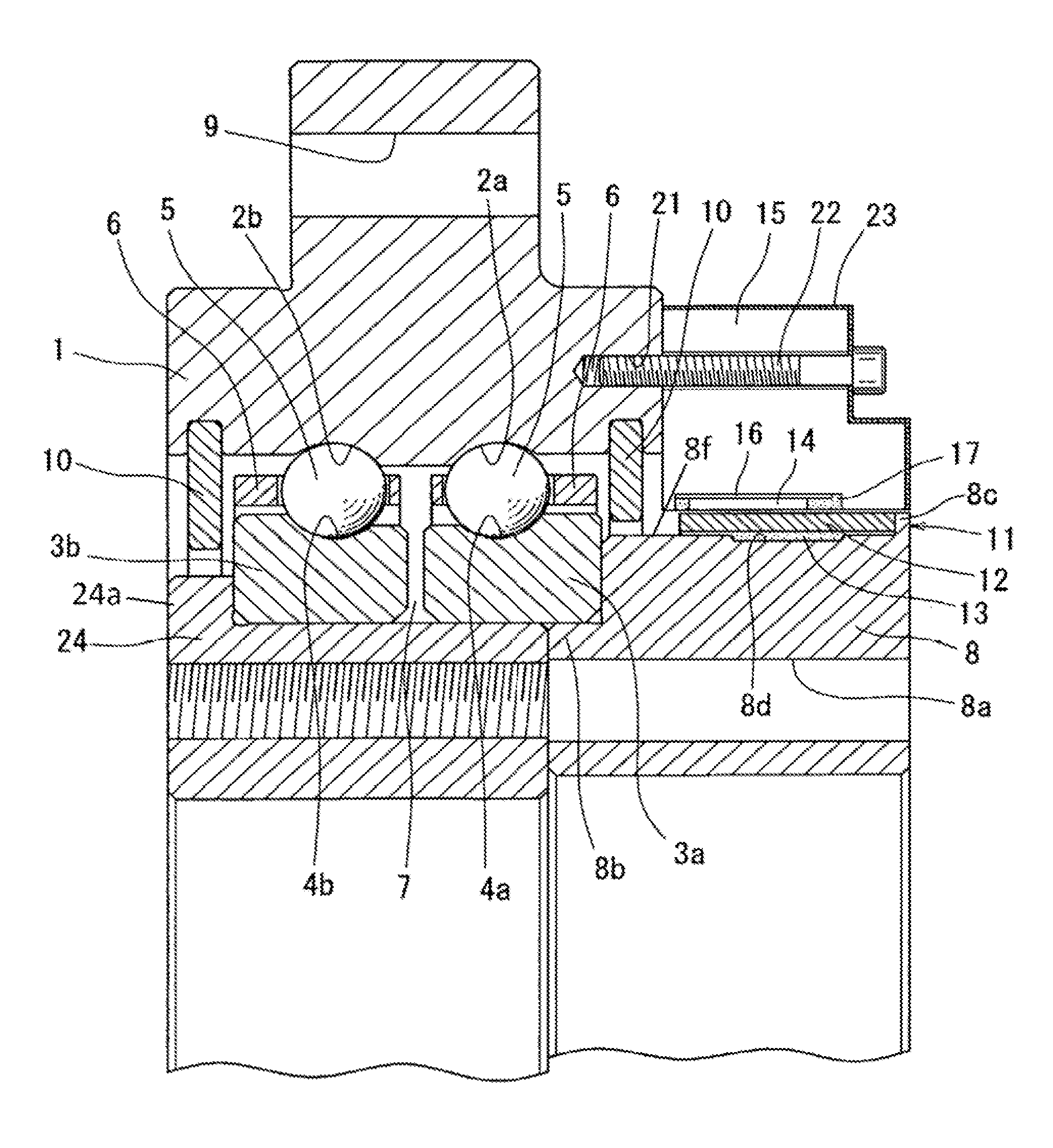
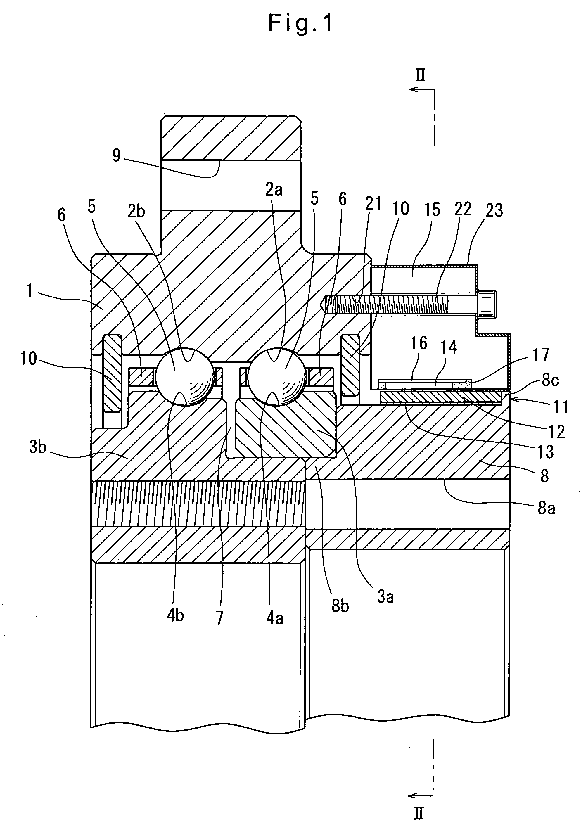
[0080]Now the embodiments of the invention are described with reference to the drawings. First, the rolling bearing with a rotational speed sensor according to the first embodiment, shown in FIGS. 1 to 4, is a double row ball bearing comprising, as shown in FIG. 1, a stationary outer race 1 having two raceways 2a and 2b formed in the radially inner surface thereof, two separate rotating inner races 3a and 3b having raceways 4a and 4b formed on the radially outer surfaces of the respective inner races 3a and 3b so as to radially oppose the respective raceways 2a and 2b of the outer race 1, and two rows of balls 5 as rolling elements retained by a retainer 6 with the respective rows of balls 5 disposed between the raceways 2a and 2b of the outer race 1 and the raceways 4a and 4b of the inner races 3a and 3b. The inner race 3b has a small-diameter outer surface on which the other inner race 3a is fitted with an axial gap 7 present therebetween. A preload that tends to reduce this gap 7...


PUM


Abstract

The object is to produce a magnetic encoder having a large outer diameter at a low cost, provide a sensor case which is compact in size and can be easily mounted and dismounted with a sensor element received therein, and to provide a double row rolling bearing with a preload application device and a rotational speed sensor which comprises a small number of parts and thus can be assembled easily. A magnetic member 12 of the magnetic encoder 11 is made of a magnetic material bound by rubber. The magnetic member 12 is bonded to an annular presser member 8, which also serves as a metal core, by an adhesive 13, thus eliminating the need for a mold and other facilities for vulcanization bonding. This makes it possible to manufacture a magnetic encoder 11 with a large outer diameter at a low cost.

Description

TECHNICAL FIELD[0001]This invention relates to a rolling bearing with a rotational speed sensor.BACKGROUND ART[0002]Some rolling bearings for supporting e.g. rotary shafts of various rotary devices carry a rotational speed sensor for detecting the rotational speed (number of revolutions per unit time) of the rotary shaft. Such a rolling bearing with a rotational speed sensor includes a magnetic encoder comprising a metal core mounted to one of inner and outer races that rotates, and an annular magnetic member magnetized such that different magnetic poles are alternately arranged in the circumferential direction and fixed to the metal core, and a sensor element fixed to the stationary race for detecting changes in magnetic poles when the magnetic encoder rotates, thereby detecting the rotation of the rotating race.[0003]The magnetic member of the magnetic encoder ordinarily comprises a magnetic material such as a ferrite and a binder such as a thermoplastic resin or rubber. The mixtu...

Claims


Application Information

Patent Timeline
Patent Type & Authority Patents(United States)
IPC IPC(8): G01B7/30
CPCF16C19/18G01P3/443G01P3/487F16C41/007F16C33/60F16C2300/14F16C19/184G01D2205/80
Inventor ITO, HIROYOSHITAKADA, SEIICHI
Owner NTN CORP
Why Eureka
Try Eureka