Laser-guided positioning device

a positioning device and laserguide technology, applied in the direction of distance measurement, instruments, using reradiation, etc., can solve the problems of difficult to accurately position the outermost end of the aerial extension ladder of the type utilized in firefighting vehicles, and the operator of the ladder positioning control is difficult to assess how

Inactive Publication Date: 2011-07-26
CARL KEITH D
View PDF36 Cites 23 Cited by
  • Summary
  • Abstract
  • Description
  • Claims
  • Application Information

AI Technical Summary

Problems solved by technology

The accurate positioning of the outermost end of an aerial extension ladder of the type utilized in firefighting vehicles is often difficult because of the considerable distance between the operator who is controlling positioning of the aerial ladder and the outer end of the ladder.
That considerable distance renders it difficult for the operator of the ladder positioning controls to assess how close the outermost end of the extending aerial ladder is relative to its intended destination position.

Method used


Image

  • Laser-guided positioning device
  • Laser-guided positioning device
  • Laser-guided positioning device

Examples


first embodiment

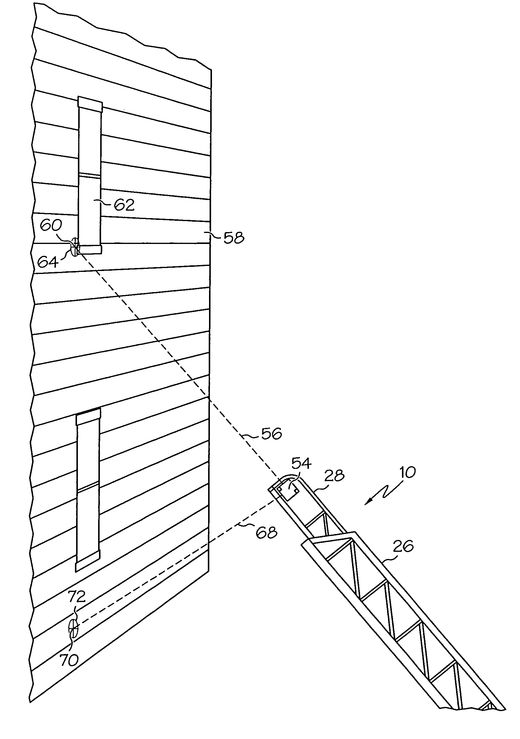
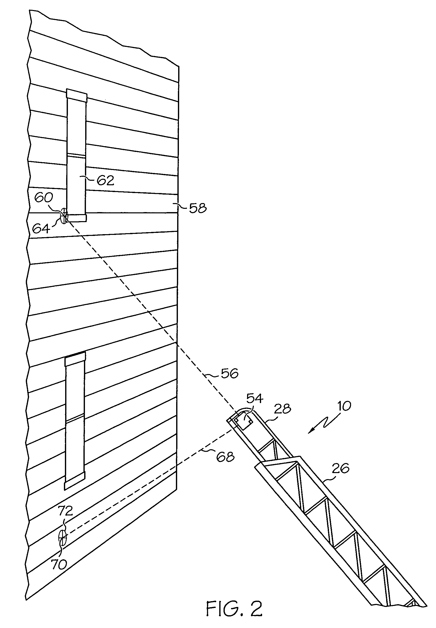
[0035]The structure of positioning device 54 is shown in FIGS. 5 and 6. A generally rectangular housing 74 contains a pair of laser light beam emitters 76, 78 that fixed in position and that have their axes oriented perpendicular to each other. The laser light beams 56, 68 that emanate from emitters 76, 78, respectively, are also perpendicular to each other and each passes through a respective cover holder 80, 82 that is threadedly secured to a respective end wall 84, 86 of the housing. Power is supplied to the laser beam emitters from a suitable 12-volt DC power source (not shown) through a branched conduit 88. The power source can include a regulated power supply (not shown), such as a 3-volt regulated power supply, as necessary to regulate the magnitude of the voltage required for the proper operation of the laser beam emitters.

[0036]Housing 74 includes three openings 90, 92, 94 through which respective securing bolts or screws can pass to attach the housing to an outermost end o...

fourth embodiment

[0044]FIG. 10 is a top plan view of a positioning device in accordance with the present invention, again with the top wall removed to show the interior arrangement of the laser light emitters. In this embodiment housing 162 is of generally triangular form within which two laser light emitters 98, 160 are positioned adjacent a corner of the housing so that the emitted laser beams are at a 45° angle to define converging and crossing laser light beams. A third laser light emitter 164 is positioned laterally from the first and second emitters to emit a laser light beam that is offset from laser light emitter 98 to extend outwardly from a third side of the housing. The third laser light emitter is housed in a separate enclosure 166 that is pivotably carried by the main housing 162 to pivot about pivot axis 168, to thereby allow the laser light beam from third emitter 164 to always point in a downward direction. This arrangement allows the outermost tip of an extension ladder to be positi...


PUM


Abstract

A positioning device for enabling a user to accurately position the outermost end of an extendable member, such as an extension ladder, relative to a fixed, elevated position. The device includes laser light sources that provide angularly disposed laser light beams that terminate at desired points when the outermost end of the extendable member is adjacent to the desired end position. A first laser light beam is arranged to extend parallel to the longitudinal axis of the extendable member, and a second laser light beam is arranged to extend at a predetermined angle relative to the first laser light beam.

Description

BACKGROUND OF THE INVENTION[0001]1. Field of the Invention[0002]The present invention relates to a positioning device for attachment to an extendable member in order to enable a user to easily and accurately position the outermost end of the extendable member adjacent to a desired end position.[0003]2. Description of the Related Art[0004]The accurate positioning of the outermost end of an aerial extension ladder of the type utilized in firefighting vehicles is often difficult because of the considerable distance between the operator who is controlling positioning of the aerial ladder and the outer end of the ladder. At full extension, typical aerial ladders are capable of reaching vertical heights of up to about 110 feet or more, depending upon the particular ladder design. That considerable distance renders it difficult for the operator of the ladder positioning controls to assess how close the outermost end of the extending aerial ladder is relative to its intended destination pos...

Claims


Application Information

Patent Timeline
Patent Type & Authority Patents(United States)
IPC IPC(8): G01C3/00G01C5/00G01B11/00
CPCB66C13/46E06C5/34G01C15/002G01S17/875G01S17/88Y10S33/21
Inventor CARL, KEITH D.
Owner CARL KEITH D
Why Eureka
Try Eureka