Electrical submersible pump with equally loaded thrust bearings and method of pumping subterranean fluid

a thrust bearing and submerged technology, applied in the direction of piston pumps, positive displacement liquid engines, borehole/well accessories, etc., can solve the problems of the thrust bearing diameter and thus the load bearing capacity, and the attempts to provide equal loading distribution

Inactive Publication Date: 2011-08-02
BAKER HUGHES INC
View PDF26 Cites 29 Cited by
  • Summary
  • Abstract
  • Description
  • Claims
  • Application Information

AI Technical Summary

Problems solved by technology

Size constraints in a producing well limit the thrust bearing diameter and thus its load bearing capacity.
However these attempts have not been able to provide equal loading distribution.

Method used


Image

  • Electrical submersible pump with equally loaded thrust bearings and method of pumping subterranean fluid
  • Electrical submersible pump with equally loaded thrust bearings and method of pumping subterranean fluid
  • Electrical submersible pump with equally loaded thrust bearings and method of pumping subterranean fluid

Examples


Embodiment Construction

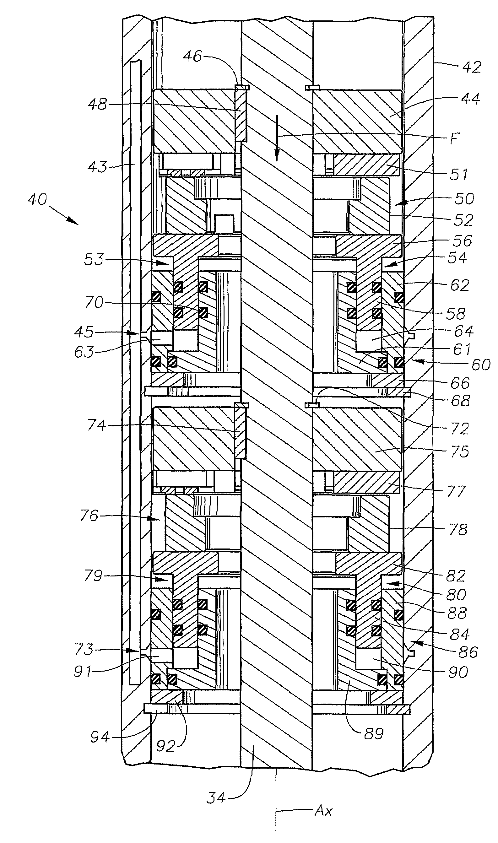
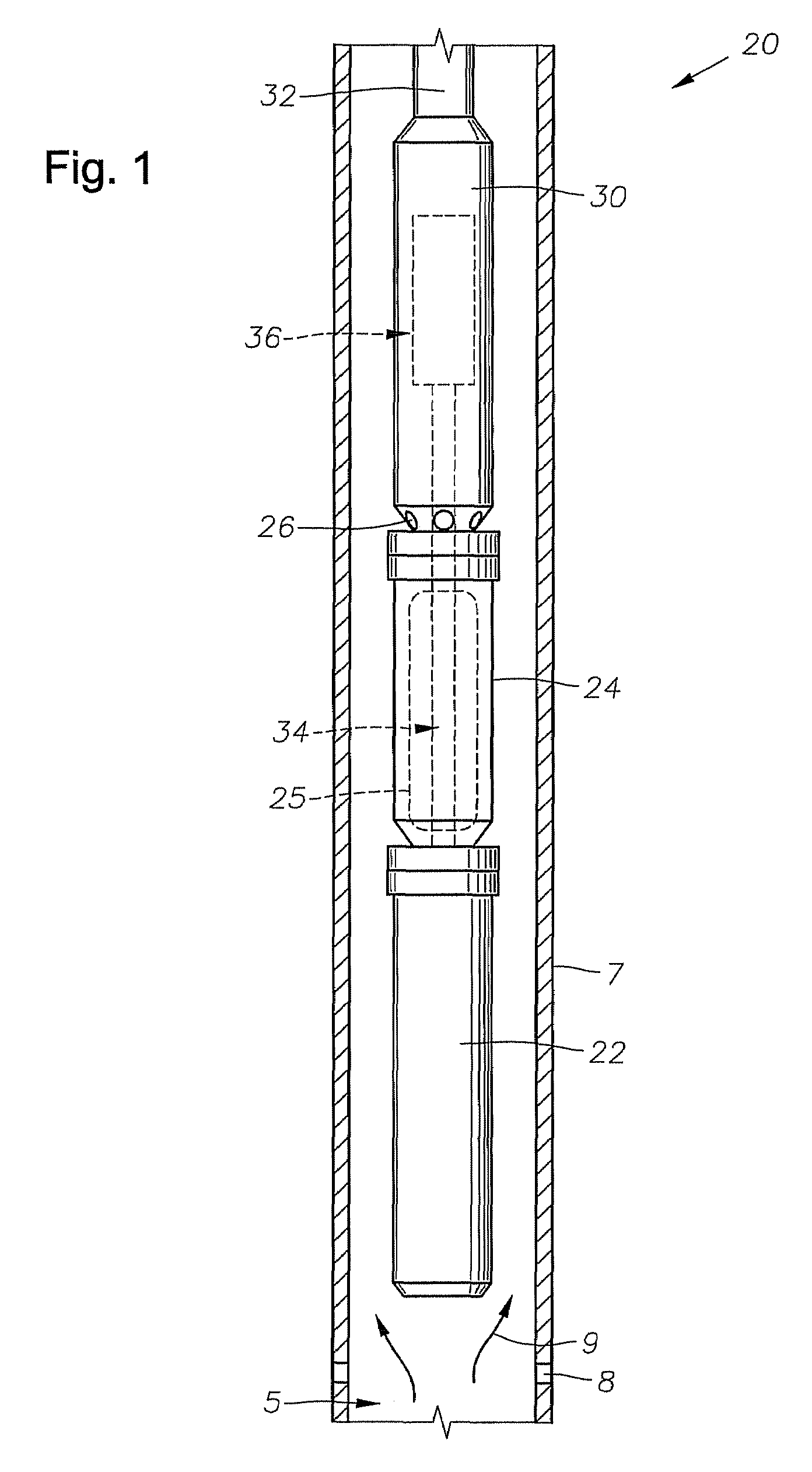
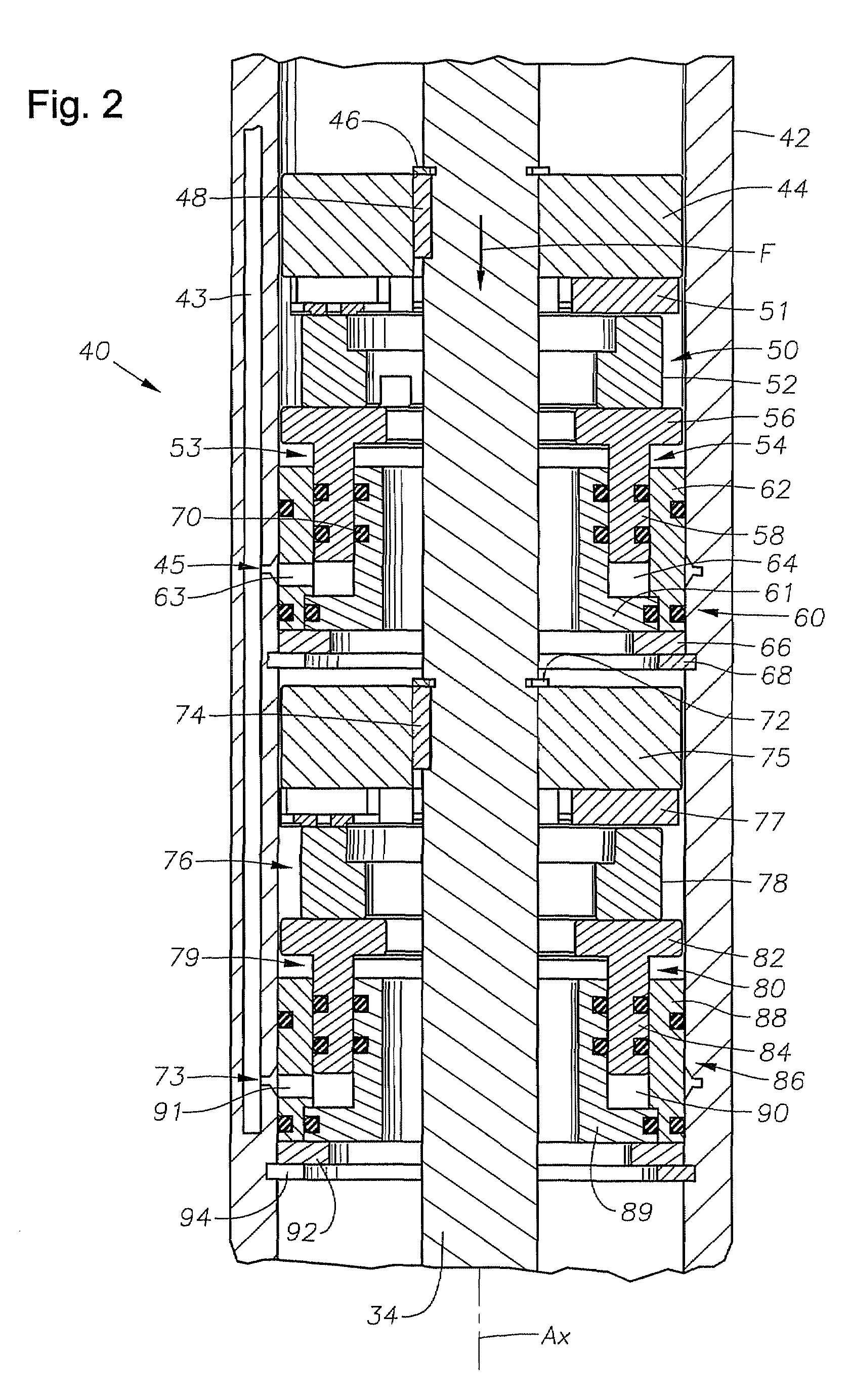
[0008]The present invention will now be described more fully hereinafter with reference to the accompanying drawings in which embodiments of the invention are shown. This invention may, however, be embodied in many different forms and should not be construed as limited to the illustrated embodiments set forth herein; rather, these embodiments are provided so that this disclosure will be thorough and complete, and will fully convey the scope of the invention to those skilled in the art. Like numbers refer to like elements throughout. For the convenience in referring to the accompanying figures, directional terms are used for reference and illustration only. For example, the directional terms such as “upper”, “lower”, “above”, “below”, and the like are being used to illustrate a relational location.

[0009]It is to be understood that the invention is not limited to the exact details of construction, operation, exact materials, or embodiments shown and described, as modifications and equ...


PUM


Abstract

A rotary pump having thrust bearings includes a system for equalizing the loading on the thrust bearings. The thrust bearings are each supported on pistons that are in fluid communication with a hydraulic circuit. The hydraulic circuit has substantially the same pressure throughout, thereby floating each piston at the same pressure to provide an equal support force to each thrust bearing via each piston.

Description

FIELD OF THE INVENTION[0001]The present disclosure relates in general to electrical submersible well pumps, and in particular to a system and method for equally distributing forces applied to thrust bearings in a centrifugal pump.BACKGROUND OF THE INVENTION[0002]Electrical submersible pumps (ESP) are normally installed on the bottom end of jointed production tubing within a cased wellbore and powered by a power cable typically attached to the outside of production tubing. In this configuration, an annulus is formed between the tubing and the wellbore casing and the produced fluids are pumped up the production tubing to the surface.[0003]The ESP pumps typically have a large number of stages, each stage having a stationary diffuser and a rotating impeller. The rotating impellers exert a downward thrust as the fluid is moved upward. The downward force is generally handled by a thrust bearing radially mounted on the pump shaft. Size constraints in a producing well limit the thrust beari...

Claims


Application Information

Patent Timeline
Patent Type & Authority Patents(United States)
IPC IPC(8): E21B43/00F16C17/04F04B35/04F04B17/00
CPCE21B43/128F16C17/04F16C2352/00F16C41/02E21B43/00F04B17/00F04B35/04
Inventor PARMETER, LARRY J.STRATTAN, SCOTT C.CHILCOAT, DAVID W.
Owner BAKER HUGHES INC
Why Eureka
Try Eureka