Pump bearing arrangement

A bearing device and pump bearing technology, applied in the field of pump bearing devices, can solve the problems of poor radial heat dissipation, insufficient heat dissipation along the radial direction, etc.

Inactive Publication Date: 2010-08-18
OERLIKON LEYBOLD VACUUM
View PDF1 Cites 33 Cited by
  • Summary
  • Abstract
  • Description
  • Claims
  • Application Information

AI Technical Summary

Problems solved by technology

Therefore, heat dissipation in the radial direction will not be adequate
Especially since bearings are generally in 1×10 -3 to 10 -10 Operates at low pressure of mbar, so radial heat dissipation is very poor

Method used


Image

  • Pump bearing arrangement
  • Pump bearing arrangement

Examples


Embodiment Construction

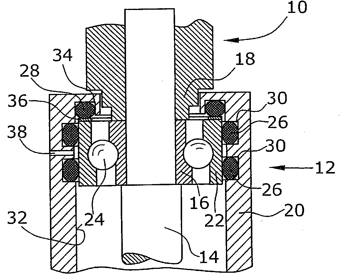
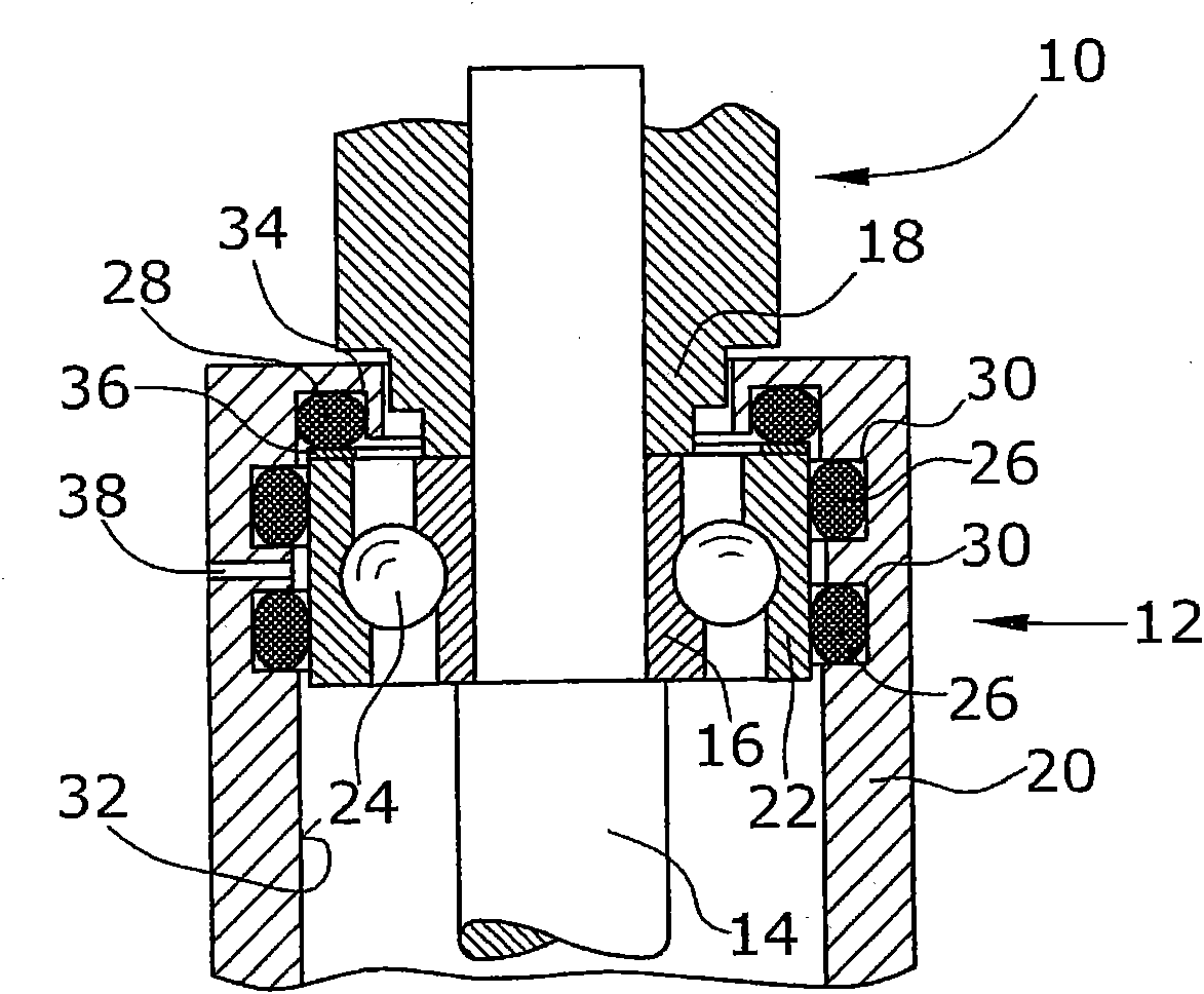
[0019] The figures show a preferred embodiment of the bearing arrangement 12 arranged in an upper position, ie facing the rotor 10 . The rotor 10 is connected for common rotation with a rotor shaft 14 . Arranged for common rotation on the rotor shaft 14 is a grooved ball bearing inner bearing housing 16 held in place by the rotor and stub shaft 18 .

[0020] The upper bearing arrangement 12 is arranged in an axle box 20 which, in the described embodiment, is substantially cylindrical. The outer bearing ring 22 is arranged inside the axle housing 20 . Arranged between the two bearing rings 16 , 22 is a spherical bearing body.

[0021] In a first embodiment, the outer bearing ring 22 is connected to the axlebox 20 by means of two radially vibrating elements 26 formed as elastic O-rings. Further provided is an axial vibration element 28 which is preferably also formed as an elastic O-ring. The two radial vibration elements 26 are respectively arranged in corresponding grooves...


PUM


Abstract

The invention relates to a pump bearing arrangement suitable particularly for rapidly rotating pumps, such as turbomolecular pumps, having a pump rotor (10) connected to a rotor shaft. The rotor shaft (14) is supported in a shaft housing (20) by two bearing devices (12). Each bearing device (12) has an inner bearing ring (16) connected to the rotor shaft (14) and an outer bearing ring (22) connected to the shaft housing (20). Bearing supports (24) are disposed between the two bearing rings. According to the invention, at least one vibration element (26) is provided between the outer bearing ring (22) and the shaft housing (20), serving for damping and further having a thermal conductivity of at least 0.3 W / mK for dissipating heat.

Description

technical field [0001] The invention relates to a pump bearing arrangement particularly suitable for fast rotating pumps such as turbomolecular pumps. Background technique [0002] Pumps such as turbomolecular pumps include a pump rotor connected to a rotor shaft. The rotor shaft is supported in the shaft housing via two bearing arrangements. The two bearing arrangements typically each comprise a ball bearing. The inner bearing rings and the respective bearing shells of the two ball bearings are fixedly connected to the rotor shaft. Both the outer bearing ring and the respective bearing shell are axially connected to the axlebox, or are arranged axially abutting eg an annular projection of the axlebox. The two bearing arrangements are axially staggered. In the radial direction, the outer bearing ring is usually not arranged directly adjoining the axlebox. Instead, an annular gap is provided between the outer bearing ring and the axle housing. In an annular groove forme...

Claims


Application Information

Patent Timeline
Patent Type & Authority Applications(China)
IPC IPC(8): F04D19/04F04D29/66F16C27/06F16C35/077
CPCF16C27/066F04D29/668F16C35/077F04D29/059F04D19/042F16C19/163F16C2360/45
Inventor 赖纳·赫尔策马库斯·亨利罗伯特·施托勒
Owner OERLIKON LEYBOLD VACUUM
Why Eureka
Try Eureka