
Hybrid laser processing apparatus

a laser processing and hybrid technology, applied in the direction of manufacturing tools, cleaning using liquids, welding/soldering/cutting articles, etc., can solve the problem that the diameter of the liquid column cannot be reduced to the desired diameter

Inactive Publication Date: 2010-05-06
SHIBUYA IND CO LTD
View PDF12 Cites 34 Cited by
  • Summary
  • Abstract
  • Description
  • Claims
  • Application Information

AI Technical Summary

Benefits of technology

[0005]Here, the smaller the diameter of the liquid column is, the more the liquid column is disturbed by air current generated around the liquid column, resulting in the length of the liquid column that can be kept in a stable state without diffusion being shortened. Accordingly, there is a problem in that the diameter of the liquid column cannot be reduced to a desired diameter.

Problems solved by technology

Accordingly, there is a problem in that the diameter of the liquid column cannot be reduced to a desired diameter.

Method used


Image

  • Hybrid laser processing apparatus
  • Hybrid laser processing apparatus
  • Hybrid laser processing apparatus

Examples


Embodiment Construction

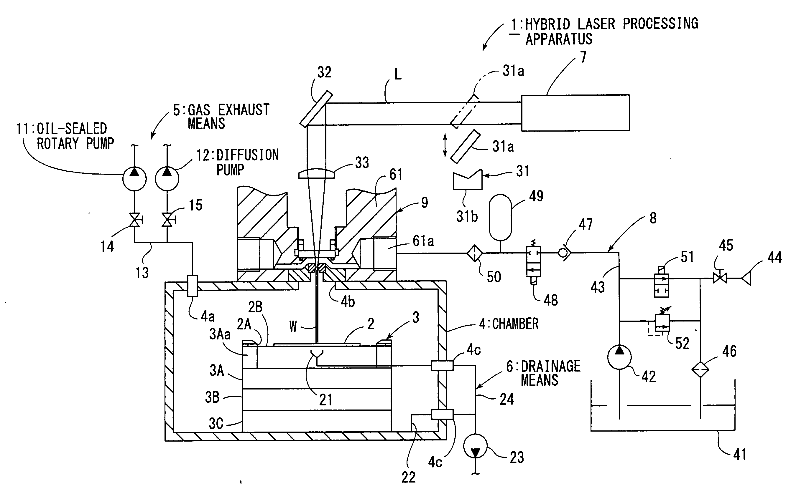
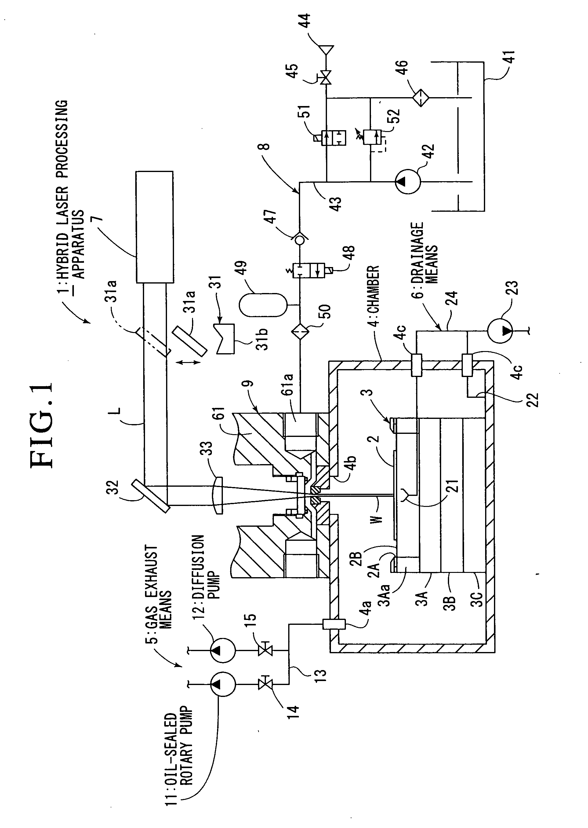
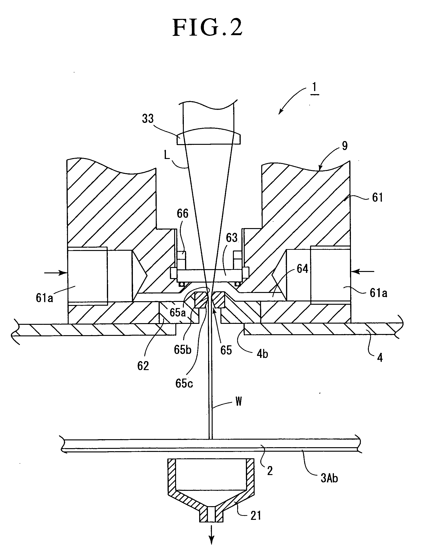
[0009]Hereinafter, description will now be given of an embodiment shown in the drawings. FIG. 1 shows a hybrid laser processing apparatus 1 according to the present invention, which cuts a workpiece 2 into a required shape by guiding laser beam L to a liquid column W formed by jetting water as a liquid.

[0010]This hybrid laser processing apparatus 1 includes: a processing table 3 holding the workpiece 2; a chamber 4 accommodating the processing table 3; gas exhaust means 5 for bringing the inside of the chamber 4 into a vacuum state; drainage means 6 for draining water in the chamber; a laser oscillator 7 that oscillates laser beam L; liquid supply means 8 for supplying high-pressure water; and a processing head 9 that jets water toward the workpiece 2 in the form of a liquid column W and guides the laser beam L to the liquid column W, and they are controlled by controlling means not shown.

[0011]This embodiment is constructed so that it cuts a thin semiconductor wafer as the workpiec...


PUM

PropertyMeasurementUnit
diameteraaaaaaaaaa
diameteraaaaaaaaaa
diameteraaaaaaaaaa

Abstract

A processing table 3 holding a workpiece 2 is accommodated in a chamber 4 with a gas-tight condition kept, and a liquid column W is jetted to an upper surface of this chamber 4, and a processing head 9 that guides laser beam L to the liquid column W is secured to the upper surface of this chamber 4. Gas exhaust means 5 in which an oil-sealed rotary pump 11 and a diffusion pump 12 are provided in parallel is connected to the chamber 4, and the diffusion pump 12 is actuated after the actuation of the oil-sealed rotary pump 11, brining the inside of the chamber 4 into a vacuum state.Bringing the inside of the chamber 4 into a vacuum state, no gas current is generated around the liquid column W jetted from the processing head 9, making it possible to prevent turbulence of the liquid column W due to turbulence of the gas current.A liquid column having a small diameter can be jetted in a stable state.

Description

TECHNICAL FIELD[0001]The present invention relates to a hybrid laser processing apparatus, and more specifically relates to a hybrid laser processing apparatus that jets a liquid from a jet hole to the outside in the form of a liquid column, and guides laser beam to the liquid column.BACKGROUND ART[0002]Conventionally, a hybrid laser processing apparatus including a processing head having a jet hole, liquid supply means for supplying the processing head with a high-pressure liquid, and a laser oscillator that oscillates laser beam, the apparatus performing processing on a workpiece by jetting the liquid supplied from the liquid supply means from the jet hole to the outside in the form of a liquid column and guiding the laser beam to the liquid column has been known. (Patent Document 1)[0003]In such a hybrid laser processing apparatus, in order to guide laser beam in a liquid column to a workpiece, it is necessary to bring the jetted liquid column to the workpiece in a stable conditi...

Claims


Application Information

Patent Timeline
Patent Type & Authority Applications(United States)
IPC IPC(8): B23K26/14B23K26/00B23K26/12B26F3/00
CPCB23K26/0604B23K26/1224B23K26/0861B23K26/12B23K26/123B23K26/38B26F3/004B23K2101/40B23K2103/16B23K2103/42B23K2103/50Y10T83/0591B23K26/142B23K26/382B23K26/146B23K26/40B23K26/0665B23K2103/56
Inventor KOSEKI, RYOJISASAKI, MOTOI
Owner SHIBUYA IND CO LTD
Learn More