
Internal combustion engine with elevated expansion ratio

Inactive Publication Date: 2005-06-21
ROBINSON BARNETT JOEL
View PDF2 Cites 19 Cited by
  • Summary
  • Abstract
  • Description
  • Claims
  • Application Information

AI Technical Summary

Benefits of technology

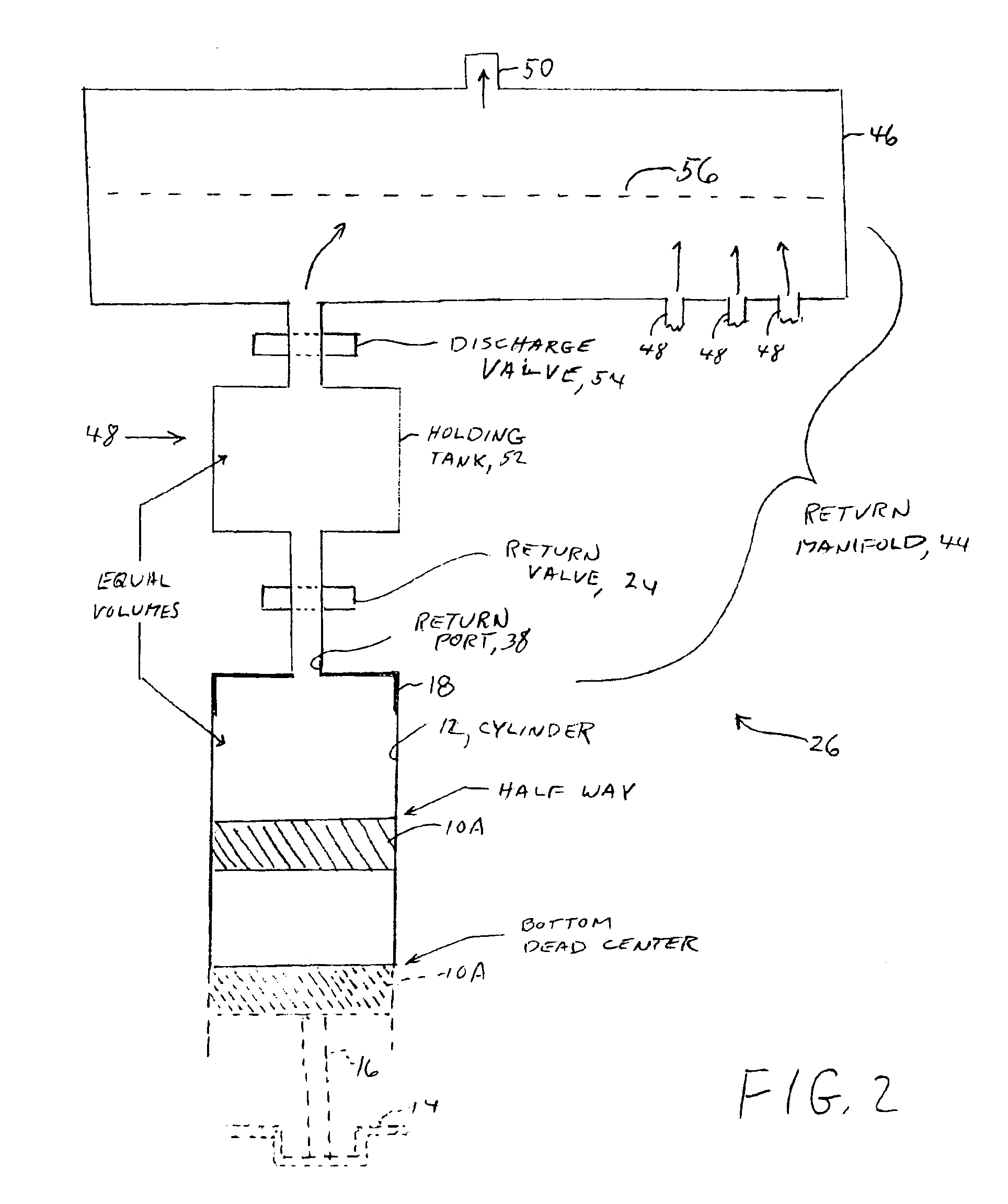
[0010]The operation of the return valves is synchronized with the operation of the intake valves. Such synchronization can be accomplished by driving the return valve of an individual one of the cylinders by an additional cam on a camshaft which operates either one or both of the intake and exhaust valves of the cylinder, or by use of a further camshaft. The return valve is open during a portion of the compression stroke of its cylinder. During an open state of the return valve, the corresponding discharge valve is closed, and the interior space of the cylinder connects via the return port to the interior space of the corresponding holding tank. This effectively enlarges the interior size of the cylinder during the portion of the compression stroke when the return valve is open. The volume of the holding tank is essentially equal to the volume of the cylinder at the point in time wherein the piston has moved approximately half way along the compression stroke. Therefore, at this point in time, half of the charge of the cylinder, namely the air fuel mix (of the gasoline engine) or the air (of the diesel engine) is located in the cylinder and the other half of the charge is located in the holding tank.
[0011]Thereupon, the return valve is closed, and the compression stroke continues with only half of the charge being present in the cylinder. The withdrawn charge is held within the holding tank until a later moment when it can be discharged into the central chamber of the return manifold. The discharging is accomplished by an opening of the discharge valve. In the practice of the invention, the discharging of the returned charges of the various holding tanks is accomplished in a manner which encourages a relatively smooth flow of the returned charges from the return manifold into the inlet to the carburetor or the fuel-injection assembly. The smooth flow of the returned air or air-fuel mix ensures that subsequent metering of the air or air-fuel mix can be accomplished in a normal manner without disruption by the process of extracting air or air-fuel mix from the cylinders.
[0013]In accordance with a well-known relationship in the physics of gases, the product of the pressure of a gas times the volume of the container of the gas is proportional to the product of the temperature of the gas times the number of moles of the gas in the container. In the above noted practice of the invention, wherein half of the charge of the cylinder is removed during the compression stroke, and wherein the length of the piston has been increased for an increased expansion ratio, the pressure and temperature of the gas at the end of the compression stroke is reduced to lower values than that which would be present if no modification had been made to the length of the piston for identically sized engines in identical vehicles traveling on the same road at the same speed. Thereby, the invention enables the engine to operate with the high-efficiency associated with the higher expansion ratio while retaining the pressure, the temperature and the ignition characteristics of the charge in the cylinder to be substantially the same as that of an unmodified engine.
[0014]In modern engines, a computer is employed for regulating the air-fuel ratio as well as the total amount of air drawn into the cylinders based on such factors as the mass density and temperature of environmental air, engine speed, requested vehicular speed, and the concentration of oxygen in the exhaust gases. Since this invention retains the temperatures and pressures of the air or air-fuel mix in the compression stroke, the vehicular computer can control the quantities of air and fuel admitted to the engine in a fashion similar to that of an unmodified engine with minimal changes in programming.

Problems solved by technology

However, attempts to build such an engine have not met with commercial success.

Method used


Image

  • Internal combustion engine with elevated expansion ratio
  • Internal combustion engine with elevated expansion ratio
  • Internal combustion engine with elevated expansion ratio

Examples


Embodiment Construction

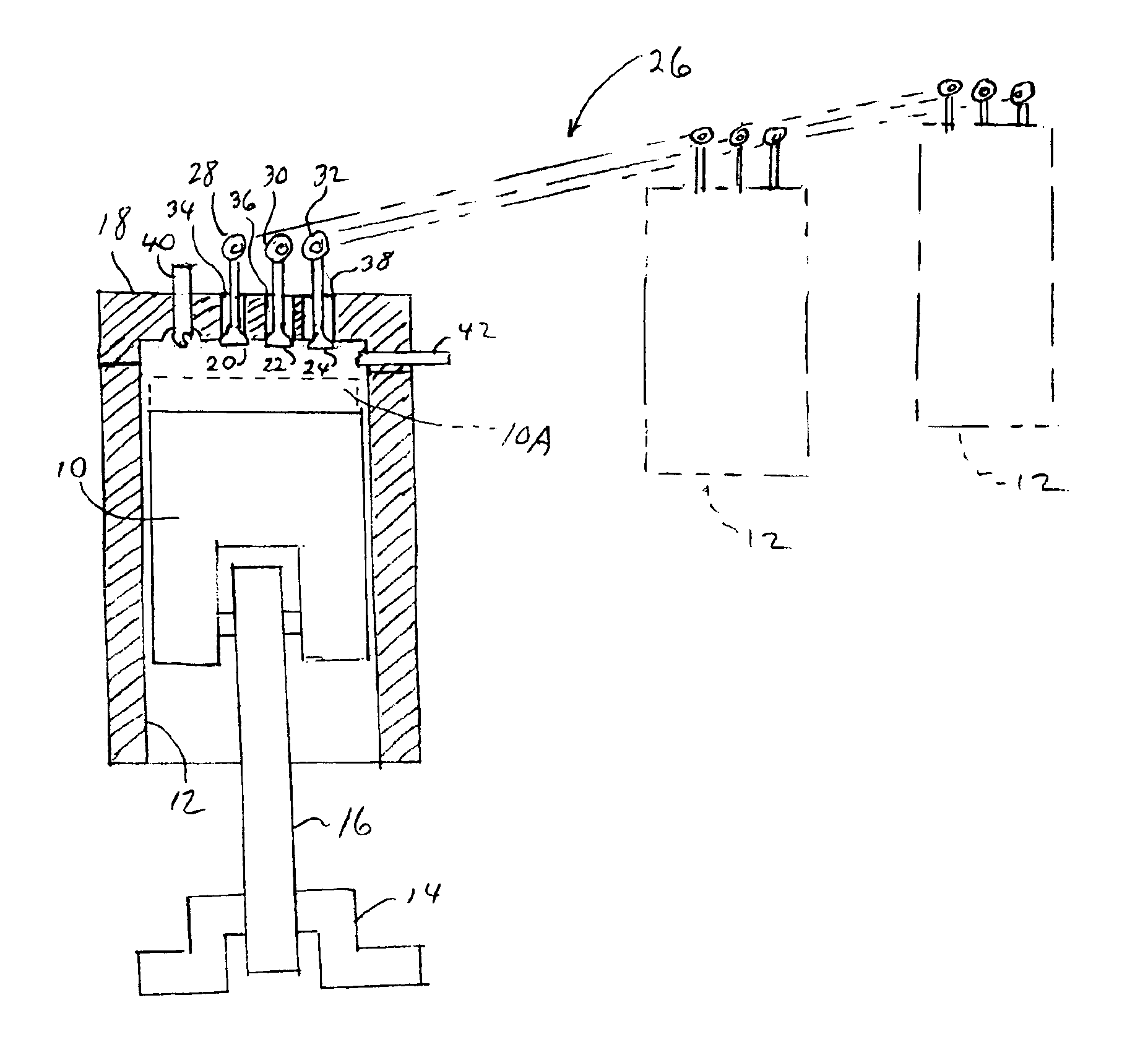
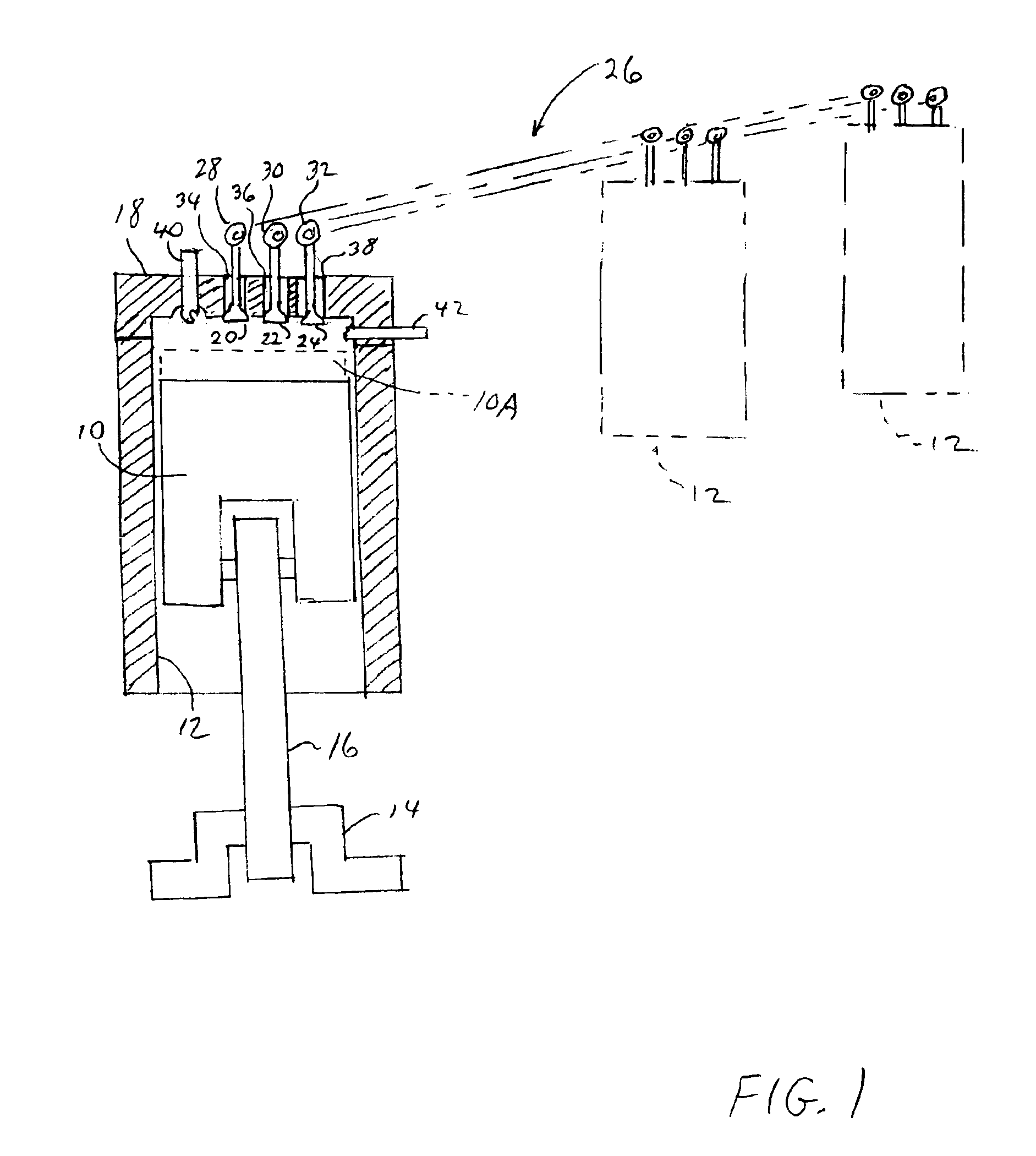
[0022]FIG. 1 shows a diagrammatic view of a piston 10 within its cylinder 12. The piston 10 is driven by a crankshaft 14 and connecting rod 16 with reciprocating motion, wherein the motion of the piston 10 is characterized by a repeating sequence of four strokes, as described above. During the induction stroke and the power (or expansion) stroke, the distance between the piston 10 and a head 18 of the cylinder 12 increases to provide for an increase in the volume of cylinder available for containing gases within the cylinder. During the compression and the exhaust strokes, the distance between the piston 10 and the head 18 decreases to provide for a decrease in the volume of the cylinder available for the containment of gases within the cylinder. The invention provides for the changing of the geometry of the piston 10 relative to the cylinder 12 by increasing the length of the piston 10 to provide for a taller piston 10A as indicated in dashed line. Typically, in the construction of...


PUM


Abstract

An Elevated Expansion-Ratio Internal Combustion Engine has a substantially standard repeating four-stroke sequence for each cylinder, and the Engine includes for each cylinder: an intake valve, a combustion-gas exhaust valve, and a vapor return valve. A return manifold for vapor connects from the return valves of respective ones of the cylinders back into a passage ahead of a beginning portion of an intake manifold. Substantially during a predetermined part of each compression stroke in the sequence of strokes, the return valve opens after a closing of the intake valve, and thereafter closes at a time within the compression stroke corresponding to a predetermined position of the piston in the cylinder.

Description

BACKGROUND OF THE INVENTION[0001]This invention relates to internal combustion engines and, more particularly, to the provision of an improved expansion cycle stroke characteristic in an internal combustion engine.[0002]A form of the internal combustion engine, generally used for powering automobiles, operates in accordance with the Otto cycle, and may be referred to herein as a gasoline engine, as distinguished from a diesel engine. The gasoline engine employs one or more cylinders, each cylinder having a piston movable therein with reciprocating motion for the driving of a crankshaft of the engine. Output power of the engine, for the driving of a load, is obtained from the rotating crankshaft. In the four-stroke form of the gasoline engine, the movement of a piston in its cylinder is characterized by four strokes, which occur in a repeating sequence, the sequence of the four strokes being; an induction stroke, a compression stroke, a power (or expansion) stroke, and an exhaust str...

Claims


Application Information

Patent Timeline
IPC IPC(8): F02B21/00F02B41/00F02B41/04F02B19/10F02B19/12F02B29/00
CPCF02B19/1014F02B19/1028F02B19/12F02B29/00F02B41/04Y02T10/142F02B2275/32Y02T10/125Y02T10/146Y02T10/12
Inventor ROBINSON, BARNETT JOEL
Owner ROBINSON BARNETT JOEL
Learn More