Dual parison blow molding and method

Active Publication Date: 2006-02-07
GRAHAM ENG CORP
View PDF23 Cites 16 Cited by
  • Summary
  • Abstract
  • Description
  • Claims
  • Application Information

AI Technical Summary

Benefits of technology

[0015]Resin flows to the radial inward coextrusion head through the assembly body without exterior flow pipes increasing the width of the body. Resin for the inner head is flowed into and through the radial outer head, to the inner head and to the annular flow passage for the inner head. Resin for the outer head is flowed into the outer head and to the annular flow passage for the outer head. Resin for the inner head flows through the outer head, past either side of the annular flow passage for the

Problems solved by technology

Accordingly, while dual layer vertical rotary blow molding machines offer increased efficiency in comparison to single parison vertical rotary blow molding machines, these machines have not previously offered the abil

Method used


Image

  • Dual parison blow molding and method
  • Dual parison blow molding and method
  • Dual parison blow molding and method

Examples


Embodiment Construction

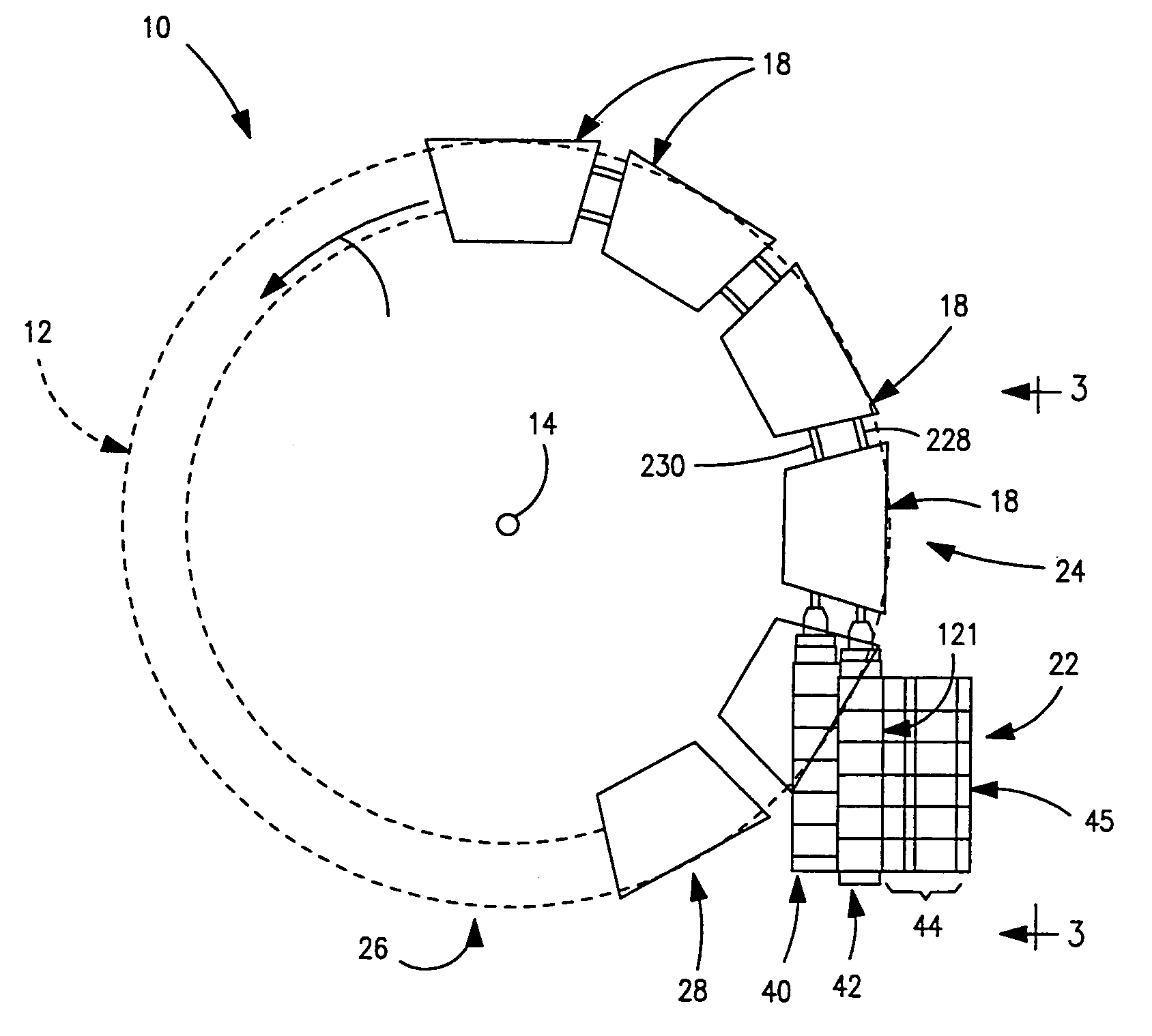
[0024]Vertical rotary blow molding machine 10 includes a rotary wheel 12 having a main shaft 14 supported in fixed bearings and a drive (not illustrated) for continuously rotating the wheel about the axis of the main shaft in the direction of arrow 16.

[0025]The wheel includes a plurality of two cavity blow molds 18 spaced circumferentially around the wheel. Machine 10 has twelve molds 18. The number of molds on wheel 12 is not material to the invention. For instance, the wheel may have nine, twelve or twenty-four molds as required.

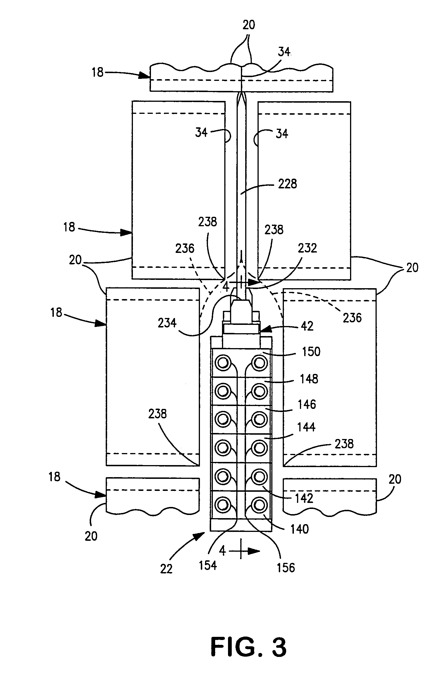
[0026]Each mold 18 includes two mold halves 20 supported on the circumference of the wheel 12 and moveable toward and away from each other along axes extending in directions parallel to the axis of rotation of the wheel at shaft 14. The mold supports and drives for opening and closing the molds are not illustrated. The wheel includes a frame supported on a floor.

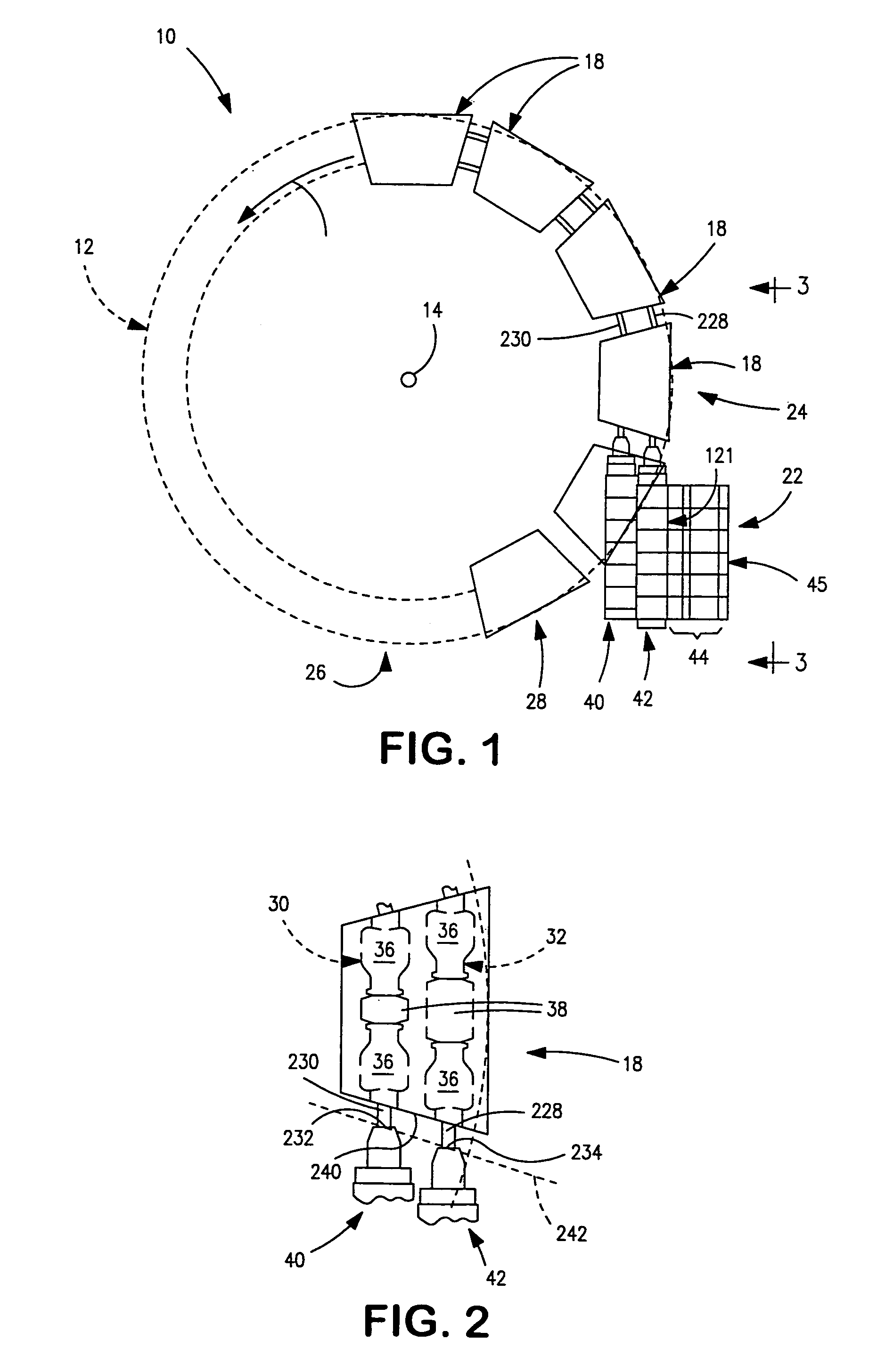
[0027]Dual parison extrusion head assembly 22 is located at the 4:00 o'clock position on wheel ...


PUM

PropertyMeasurementUnit
Timeaaaaaaaaaa
Pressureaaaaaaaaaa
Flow rateaaaaaaaaaa

Abstract

A vertical rotary blow molding machine with dual cavity molds includes two coextrusion flow heads for extruding multi-layer parisons for capture and blowing in the dual cavity molds.

Description

FIELD OF THE INVENTION[0001]The invention relates to vertical rotary blow molding machines with two cavity molds and a dual parison extrusion assembly for simultaneously extruding two parisons for capture in the mold cavities and blow molding bottles in the mold cavities, and to related methods.DESCRIPTION OF THE PRIOR ART[0002]Continuous vertical rotary blow molding machines with single cavity molds are well known. In these machines a set of molds is mounted around the circumference of a vertical wheel. A drive rotates the wheel to move open mold halves past a single parison extrusion head and then closes the molds on a parison extruded by the head to capture a portion of the parison in each mold cavity and subsequently blow the parison to form a blow molded article, typically one or two bottles.[0003]Each vertical rotary blow molding machine requires a wheel, a set of molds, an extrusion head, an extruder and piping connecting the extruder to the head. In machines blowing multi-la...

Claims


Application Information

Patent Timeline
IPC IPC(8): B29C49/04B29C47/26B29C47/28B29C49/36B29C48/09B29C48/335B29C48/34
CPCB29C47/0023B29C47/061B29C47/065B29C47/261B29C47/30B29C49/36B29C47/0014B29L2031/7158B29C49/22B29C49/48B29C2049/048B29C2049/4871B29C49/04B29C48/05B29C48/09B29C48/185B29C48/21B29C48/336B29C48/345B29C49/04108B29C49/4819
Inventor DUNDAS, DENNIS L.IVIE, KRISTOPHER J.
Owner GRAHAM ENG CORP
Why Eureka
Try Eureka