Roller drive for a conveyor system and conveyor system

a technology of roller drive and conveyor system, which is applied in the direction of roller-ways, dynamo-electric machines, supports/enclosements/casings, etc., can solve the problems of increased torque and increased power loss of roller drive, and achieve reliable security, good thermal conductivity, and improved heat transfer

Inactive Publication Date: 2011-08-02
SIEMENS AG
View PDF13 Cites 16 Cited by
  • Summary
  • Abstract
  • Description
  • Claims
  • Application Information

AI Technical Summary

Benefits of technology

[0011]The invention is based on the consideration that it is possible to increase the torque of the drive roller, if the heat emitted by the roller drive is distributed as regularly as possible in the roller tube. This allows a high level of heat emission to be achieved over the entire length of the roller tube where possible, so that despite the greater torque the temperature of the roller tube does not exceed the maximum permitted temperature at any point. A particularly good temperature distribution is present in that the heat generated by the roller drive is emitted to the roller tube over the largest possible region along the drive roller. The thermally conducting element is provided for this purpose, being connected to the roller drive and at least partially filling the hollow space within the roller tube. Some of the heat from the roller drive is induced into the thermally conducting element in this process, with the heat being emitted from there by way of thermal radiation to the roller tube. The thermally conducting element here is a stationary component, which is only in direct contact with the stator and is separated from the rotating roller tube by way of an air gap. The thermally conducting element therefore represents an extension of the roller drive, with the aid of which the heat is emitted over a longer distance in the longitudinal direction of the drive roller to the roller tube and is thus distributed more evenly.
[0013]According to a further preferred embodiment the thermally conducting element is connected by way of a thermally conducting casting compound to the stator and in particular to winding heads, in which the power loss occurs. A casting compound on the one hand allows the thermally conducting element to be secured reliably to the roller drive. A casting compound has also proven particularly advantageous, particularly where the roller drive has an uneven end face, as the casting compound fills the gaps between the profiled end face of the stator and the end surface of the thermally conducting element, thereby improving the heat transfer between the roller drive and the thermally conducting element. The casting compound used is for example a tough compound or a hardenable compound, in particular an adhesive, with good thermal conductivity.
[0014]Dissipation of the heat generated in the roller drive can also be increased by configuring the thermally conducting element in such a manner that it emits as much heat as possible to the surroundings. The thermally conducting element here has a cutout in the manner of a cone preferably inside the end surface in the direction of an opposing end face. The conical cutout enlarges the surface of the thermally conducting element, thereby increasing the quantity of heat emitted to the surroundings in the form of thermal radiation. Such a cutout also allows savings to be made on materials, resulting in a particularly economical embodiment.
[0019]The length of the thermally conducting element is preferably greater than 15% and in particular greater than 20% of the length of the stator to allow a large transfer of heat to the roller tube. The length of the thermally conducting element is tailored in particular to the existing space with longer thermally conducting elements being able to absorb more heat and resulting in better heat distribution in the drive roller.

Problems solved by technology

However a desired increase in torque cannot be achieved by enlarging the dimensions of the roller drive, as enlarging the roller drive would result in a greater power loss for the roller drive.

Method used


Image

  • Roller drive for a conveyor system and conveyor system
  • Roller drive for a conveyor system and conveyor system
  • Roller drive for a conveyor system and conveyor system

Examples


Embodiment Construction

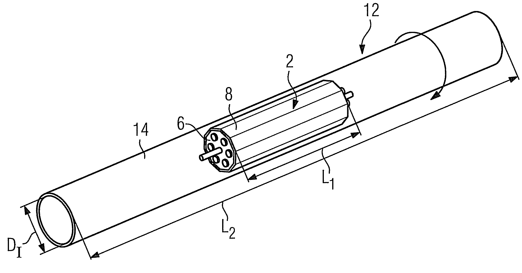
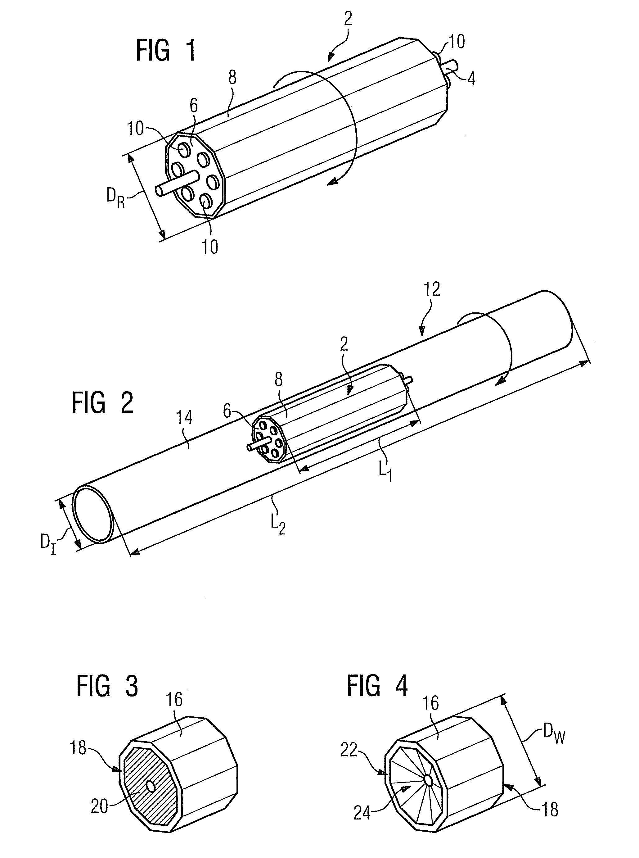
[0029]FIG. 1 shows a roller drive 2, which essentially comprises a stator 6 disposed on a shaft 4 and a rotor 8 enclosing the stator 6. The fixed stator 6 is made from an iron core, in which a number of windings 10 are disposed. The rotor 8 is disposed around the stator 6 in such a manner that it can rotate freely about the stator 6 as a result of the magnetic forces generated by the windings 10. The rotor 8 has an external diameter DR, which defines the diameter of the roller drive 2.

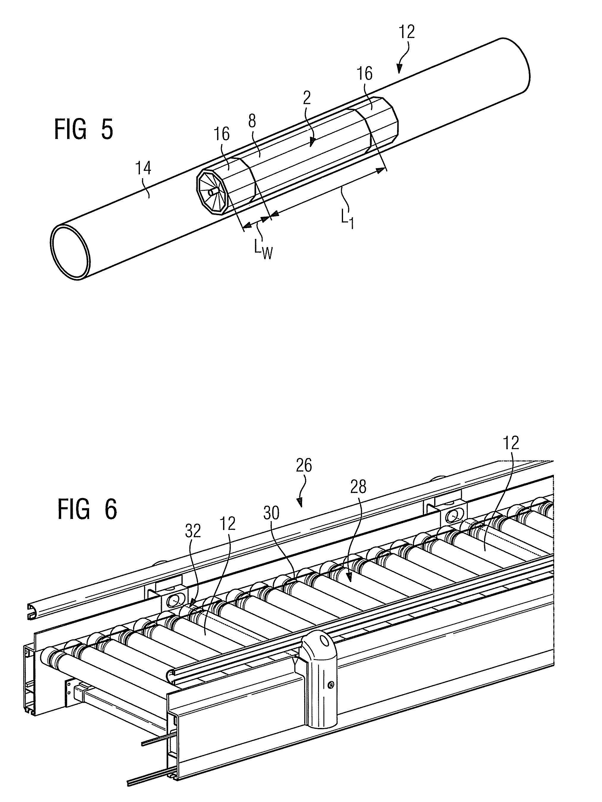
[0030]The roller drive 2 is deployed to drive a drive roller 12, which is part of a conveyor system (not shown in detail here). The drive roller 12 also comprises a roller tube 14, in which the roller drive 2 is positioned centrally in respect of a length L2 of the roller tube 14. The rotor 8 is connected by way of securing means (not shown in detail here) to the roller tube 14, so that during operation of the roller drive 2 the rotation of the rotor 8 also causes the roller tube 14 to rotate. The roll...


PUM


Abstract

A roll drive for driving a drive roller of a conveyor system has a stator which is arranged on a shaft and has a plurality of windings for generating a magnetic field, and a rotor which is arranged around the stator and is connected to a roller tub of the drive roller. A thermally conducting element is provided on the end side of the stator for dissipation of the heat which is produced during operation of the roll drive.

Description

CROSS REFERENCE TO RELATED APPLICATIONS[0001]This application is the US National Stage of International Application No. PCT / EP2007 / 064029 filed Dec. 17, 2007 and claims the benefit thereof. The International Application claims the benefits of German Patent Application No. 10 2006 060 009.6 DE filed Dec. 19, 2006, both of the applications are incorporated by reference herein in their entirety.FIELD OF INVENTION[0002]The invention relates to a roller drive for driving a drive roller of a conveyor system and a conveyor system.BACKGROUND OF INVENTION[0003]Conveyor systems comprising a number of rollers disposed parallel to one another and connected to one another by belts are used widely in industry to convey goods. Some of the rollers in the conveyor system, so-called drive rollers, contain an electric motor as part of a roller drive, with the aid of which a rotational movement of the drive roller is generated.[0004]The roller drive generally comprises a hollow rotor with permanent mag...

Claims


Application Information

Patent Timeline
Patent Type & Authority Patents(United States)
IPC IPC(8): B65G13/06
CPCB65G23/08H02K5/04H02K9/22H02K7/14H02K21/22H02K9/223
Inventor SCHWESIG, GUNTER
Owner SIEMENS AG
Why Eureka
Try Eureka