
Unified retention mechanism for CPU/socket loading and thermal solution attach

a technology of unified retention mechanism and integrated circuit package, which is applied in the direction of electrical apparatus construction details, coupling device connection, manufacturing tools, etc., can solve the problems of pin pitch and pin number limitations, pin reliability issues, and the pga package typically has a greater assembly and material cost due to the pins

Active Publication Date: 2011-08-02
INTEL CORP
View PDF12 Cites 20 Cited by
  • Summary
  • Abstract
  • Description
  • Claims
  • Application Information

AI Technical Summary

Benefits of technology

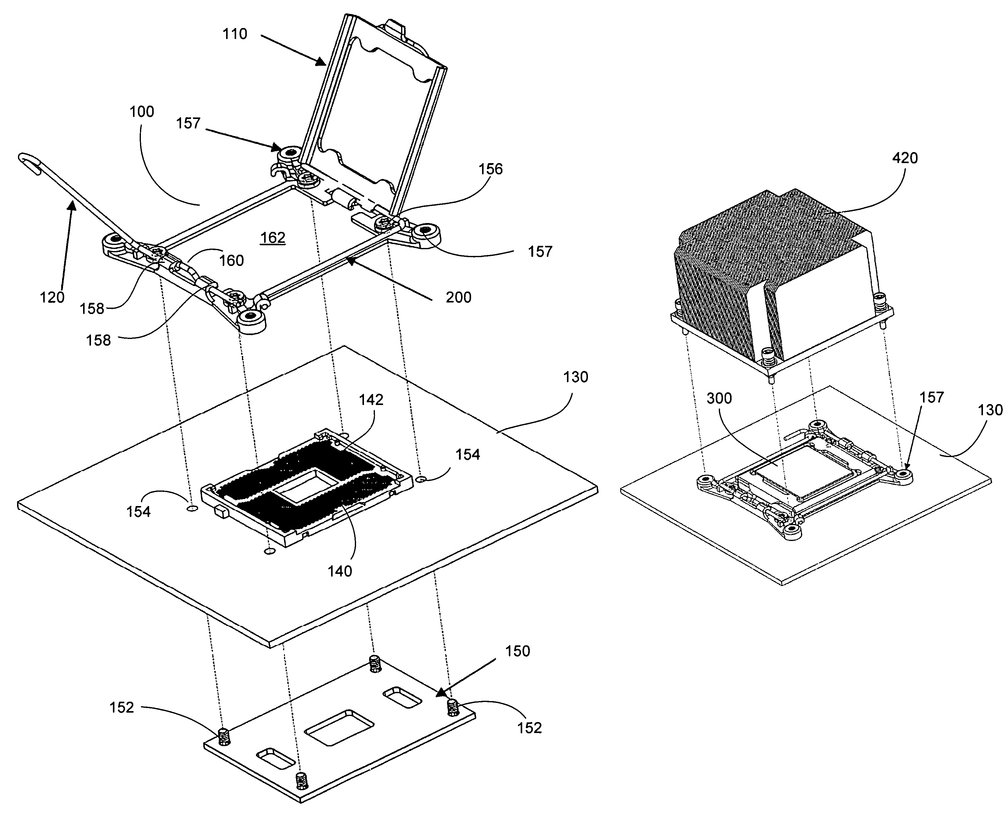
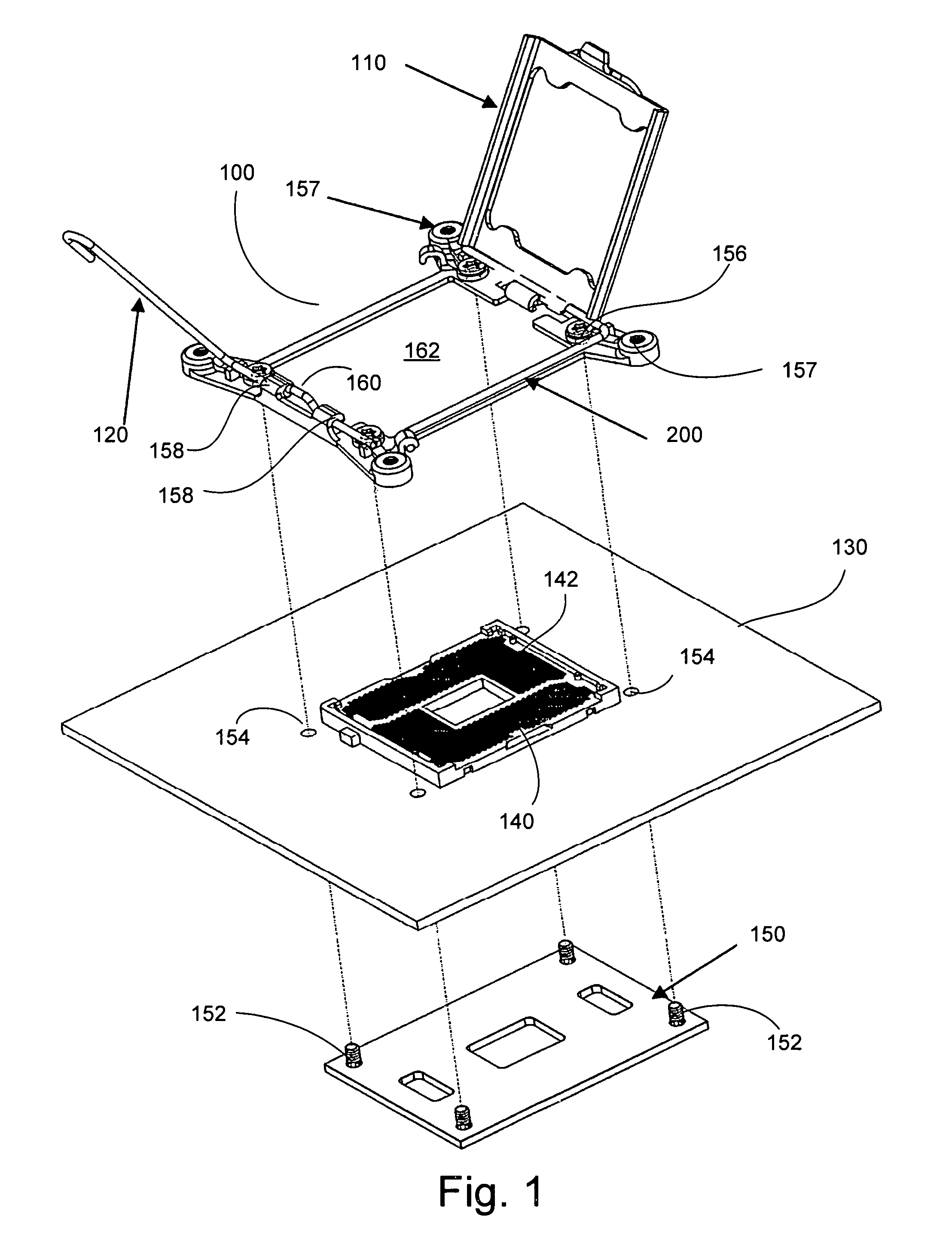
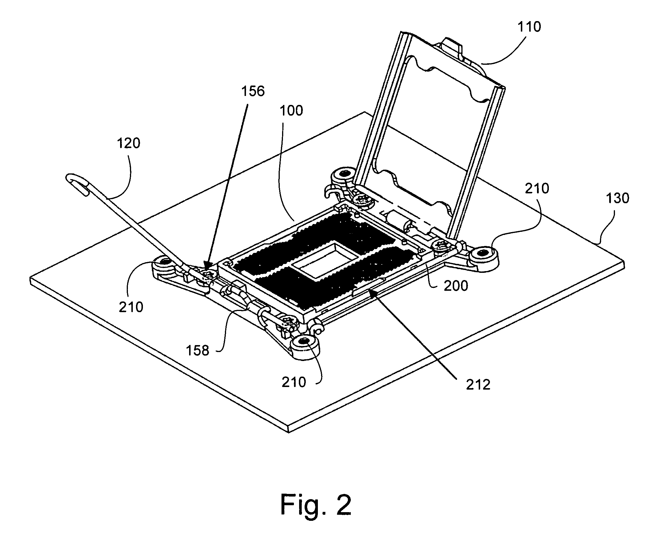
The present invention provides a new way to securely hold a CPU package in a socket. The invention is a universal retention mechanism (URM) that can be used with different types of CPU packages, such as LGA and PGA sockets. The URM eliminates the need for additional holes or fasteners in the circuit board for attaching a thermal solution device, such as a heat sink or other cooling device. The URM uses a retention frame, load plate, and load lever to forcibly press the CPU package and socket together, ensuring proper engagement of contacts. The invention allows for easy removal and replacement of the CPU package and provides a more cost-effective solution for securing a CPU package in a confined area.

Problems solved by technology

PGA packages typically have a greater assembly and material cost due to the pins.
In addition, there are limitations on the pin pitch and number of pins that can realistically be manufactured.
Unfortunately, the DSL mechanism may result in solder joint reliability issues in various shock, vibration and power cycle conditions.
In addition, it may pose challenges with scalability to accommodate larger numbers of contacts and may not easily lend itself to low profile designs.
The ILM, on the other hand, may utilize a larger back plate on the underside of the board with holes or attachment points drilled through the board for attachment of the socket and a second set of holes out further for attachment of a heatsink which may render it less desirable in system designs that have minimal clearance between the back of the board and the chassis.

Method used


Image

  • Unified retention mechanism for CPU/socket loading and thermal solution attach
  • Unified retention mechanism for CPU/socket loading and thermal solution attach
  • Unified retention mechanism for CPU/socket loading and thermal solution attach

Examples


Embodiment Construction

[0013]Reference throughout this specification to “one embodiment” or “an embodiment” means that a particular feature, structure, or characteristic described in connection with the embodiment is included in at least one embodiment of the present invention. Thus, the appearances of the phrases “in one embodiment” or “in an embodiment” in various places throughout this specification are not necessarily all referring to the same embodiment.

[0014]Furthermore, the particular features, structures, or characteristics may be combined in any suitable manner in one or more embodiments. For example, although embodiments are discussed with reference to an IC device having a package with land grid array (LGA) contacts, it will be readily apparent to those skilled in the art that other embodiments having other types of contacts may be employed without departing from the spirit and scope of the invention as hereinafter claimed.

[0015]An apparatus for removably retaining an IC package in engagement w...


PUM


Abstract

An apparatus for removably retaining an IC package in engagement with a socket such that the contacts of both the IC package and the socket are properly engaged is disclosed. Specifically, a universal retention mechanism (URM) which may be fabricated in a diecast material, may comprise a retention frame to engage a socket. A load plate hinged to the retention frame may be caused to press the socket and IC package together through force selectively applied through the use of a load lever. In addition, the frame may contain features to attach a thermal solution (e.g. a heat sink or other cooling device) directly to the frame thus eliminating the need to attach it directly to a motherboard or through a backplate.

Description

FIELD OF THE INVENTION[0001]Embodiments of the present invention are directed to sockets and, more particularly, to sockets for holding an integrated circuit package which may include attachment for a heat sink device.BACKGROUND INFORMATION[0002]Semiconductor manufacturers currently employ two primary technologies for central processing unit (CPU) packages. The first is referred to as pin grid array (PGA) sockets and the second is commonly referred to as land grid array (LGA) sockets.[0003]PGA packages typically have a greater assembly and material cost due to the pins. In addition, there are limitations on the pin pitch and number of pins that can realistically be manufactured.[0004]LGA packages may be less costly since there may be no holes, rather, pins on the LGA touch contact points on the underside of the CPU and are retained in the socket by either an integral loading scheme such as the direct socket loading (DSL) for socket T or an independent loading mechanism (ILM) with a ...

Claims


Application Information

Patent Timeline
Patent Type & Authority Patents(United States)
IPC IPC(8): H01R13/62H01R13/00
CPCH05K7/1053Y10T29/49988
Inventor ULEN, NEALLLAPITAN, DAVID
Owner INTEL CORP
Learn More