
Miniature apparatus and method for optical stimulation of nerves and other animal tissue

a technology of optical stimulation and nerves, applied in the field of optical nerve stimulation, can solve problems such as the danger of projectile accidents, the danger of using metal probes to deliver electrical stimulation to nerves of subjects, and the many limitations of electrical, mechanical, chemical and other stimulations

Inactive Publication Date: 2011-08-02
NERVESENSE LTD
View PDF132 Cites 173 Cited by
  • Summary
  • Abstract
  • Description
  • Claims
  • Application Information

AI Technical Summary

Problems solved by technology

The high static magnetic fields (B0 fields) created by an MRI machine create a danger of projectile accidents from any object having magnetic properties that may be near the MRI machine.
Using metal probes to deliver electrical stimulation to nerves of a subject poses one such danger.
Electrical, mechanical, and chemical stimulations have many limitations.
Stimulation by such methods typically results in non-specific stimulation of neurons and / or damage to neurons.
Difficulty exists in recording electrical activity from the neuron due to an electrical artifact created by the stimulus.
Such techniques do not easily lend themselves to implantable electrodes for long-term use in stimulation of neural tissue.
Unfortunately, FELs are expensive, large, awkward and unwieldy.
Further, some conventional optical systems include some magnetic materials, making them unsuitable for use near MRI systems.
In other conventional neural-stimulation systems, 110-volt AC (wall power) is used to control and / or drive the laser components, with electrical, cooling-fluid, and / or optical tethers between a delivery head and other portions of the equipment, making such systems clumsy and / or perhaps somewhat dangerous to use if relatively high voltages are present in the hand-held portion.

Method used


Image

  • Miniature apparatus and method for optical stimulation of nerves and other animal tissue
  • Miniature apparatus and method for optical stimulation of nerves and other animal tissue
  • Miniature apparatus and method for optical stimulation of nerves and other animal tissue

Examples


Embodiment Construction

[0043]Although the following detailed description contains many specifics for the purpose of illustration, a person of ordinary skill in the art will appreciate that many variations and alterations to the following details are within the scope of the invention. Very narrow and specific examples are used to illustrate particular embodiments; however the invention described in the claims is not intended to be limited to only these examples, but rather includes the full scope of the attached claims. Accordingly, the following preferred embodiments of the invention are set forth without any loss of generality to, and without imposing limitations upon the claimed invention.

[0044]In the following detailed description of the preferred embodiments, reference is made to the accompanying drawings that form a part hereof, and in which are shown by way of illustration specific embodiments in which the invention may be practiced. It is understood that other embodiments may be utilized and struct...


PUM


Abstract

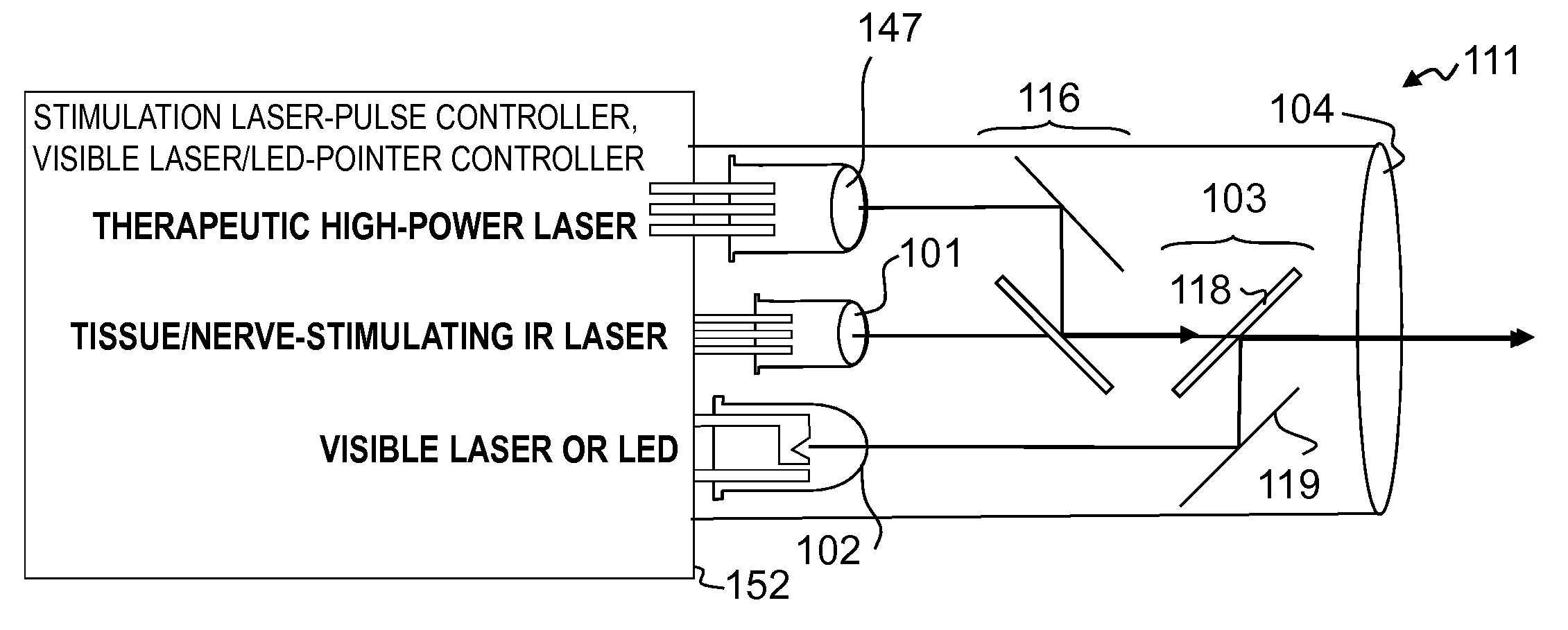
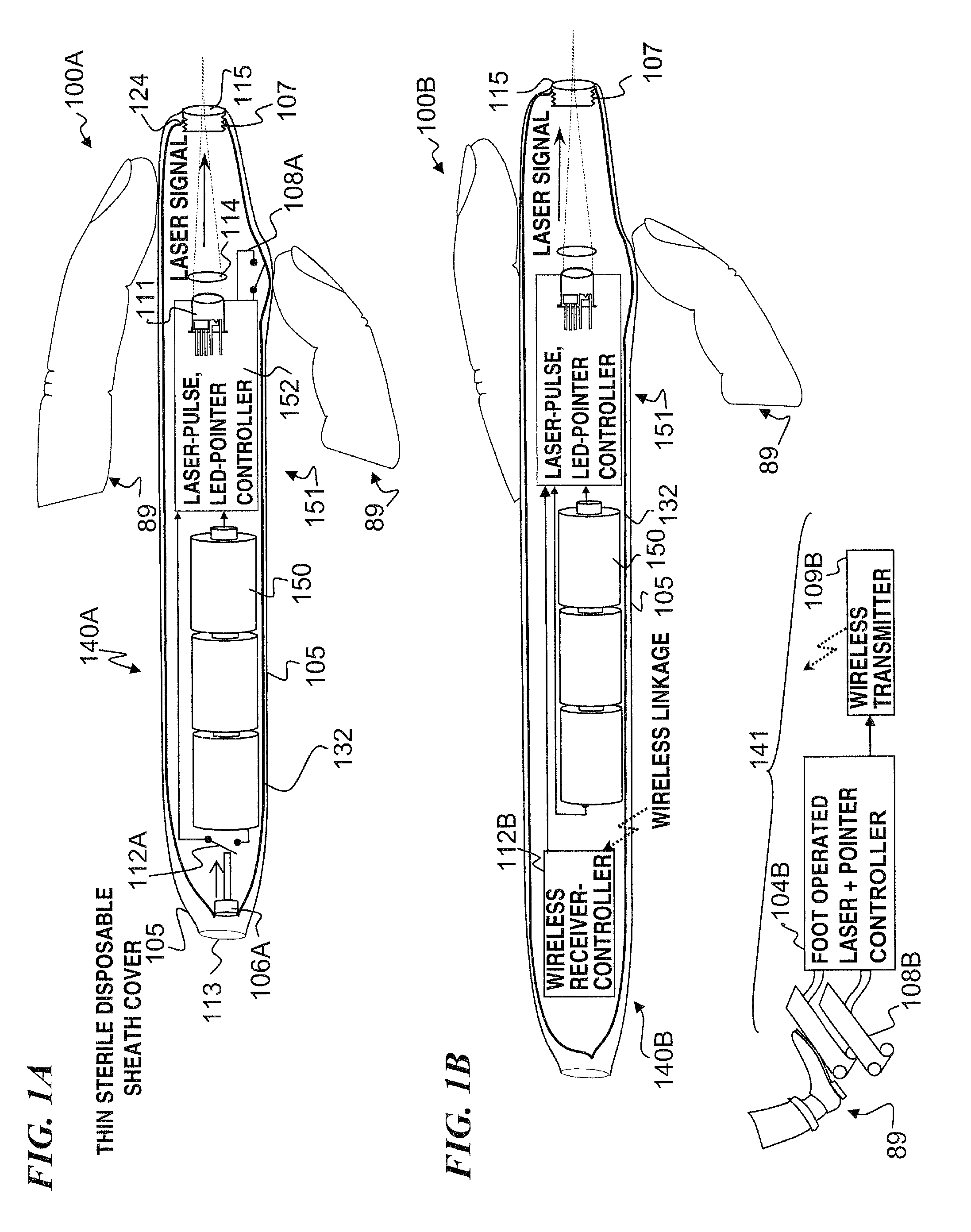
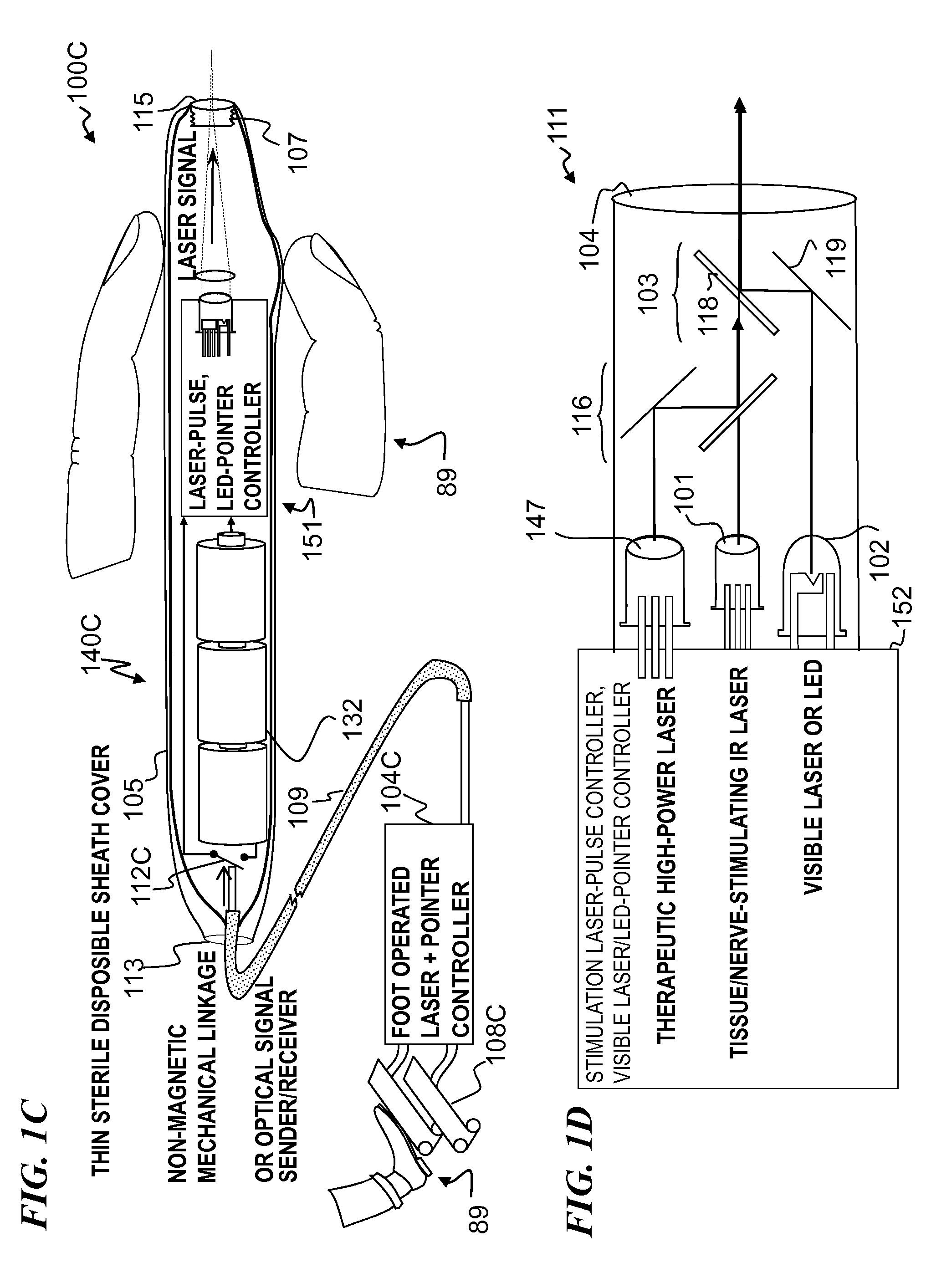
A hand-held self-contained nerve-stimulation device and method using light to provide a source of precise stimulation on one or more nerve fibers. In some embodiments, this simulation is provided through a device and method wherein a laser- or LED-light source is mounted to the handpiece. Light is passed from the light source through optical tip to simulate nerves. In some embodiments, the device is constructed from non-magnetic material such as glass, plastic or ceramics. In some embodiments, the light emanating from the optical tip can be controlled manually or automatically. In some embodiments, the handpiece contains a self-contained power source, such as batteries. In some embodiments, the handpiece is at least in part, activated by remote control in order to prevent moving the handpiece during activation. Some embodiments include a unit operable to sense a response of nerve stimulation and to suppress a laser-ablation surgery operation.

Description

CROSS-REFERENCE TO RELATED APPLICATIONS[0001]This application claims benefit of U.S. Provisional Patent Application 60 / 826,538 filed on Sep. 21, 2006, titled “MINIATURE APPARATUS AND METHOD FOR OPTICAL STIMULATION OF NERVES AND OTHER ANIMAL TISSUE,” which is incorporated herein by reference in its entirety. This application is also related to U.S. patent application Ser. No. 11 / 257,793 filed on Oct. 24, 2005 entitled “APPARATUS AND METHOD FOR OPTICAL STIMULATION OF NERVES AND OTHER ANIMAL TISSUE” (now U.S. Pat. No. 7,736,382 titled “APPARATUS FOR OPTICAL STIMULATION OF NERVES AND OTHER ANIMAL TISSUE”), and to U.S. patent application Ser. No. 11 / 536,642 filed on Sep. 28, 2006, entitled “APPARATUS AND METHOD FOR STIMULATION OF NERVES AND AUTOMATED CONTROL OF SURGICAL INSTRUMENTS,” which are each incorporated herein by reference in their entirety.FIELD OF THE INVENTION[0002]The invention relates generally to optical nerve stimulation, and more particularly to methods and miniature and / ...

Claims


Application Information

Patent Timeline
Patent Type & Authority Patents(United States)
IPC IPC(8): A61N5/06
CPCA61N5/0618A61N5/0622A61N2005/0659A61N2005/0651A61N2005/0644
Inventor WEBB, JAMES S.MIYAKE, CHARLES I.BENDETT, MARK P.LEMAIRE, CHARLES A.
Owner NERVESENSE LTD
Learn More