
Gantry, particle therapy system, and method for operating a gantry

a gantry and particle therapy technology, applied in the field of gantry, can solve the problems of increasing the design and construction effort of the mechanical structure of the gantry, and the substantial cost and construction effort, and achieve the effect of cost-effectiveness

Inactive Publication Date: 2011-08-02
SIEMENS HEALTHCARE GMBH
View PDF8 Cites 41 Cited by
  • Summary
  • Abstract
  • Description
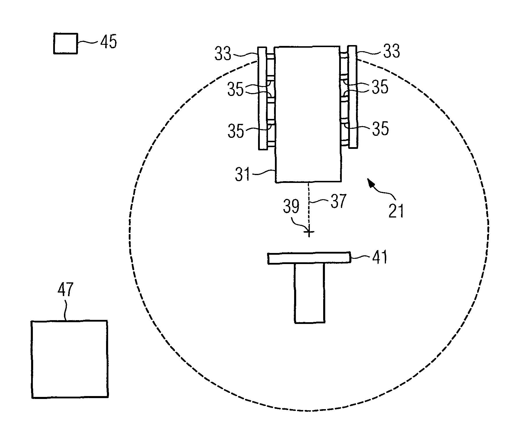
  • Claims
  • Application Information

AI Technical Summary

Benefits of technology

[0008]The present embodiments may obviate one or more of the drawbacks or limitations inherent in the related art. For example, in one embodiment, a gantry for the precise guidance of a particle beam has a lightweight and cost-effective construction.
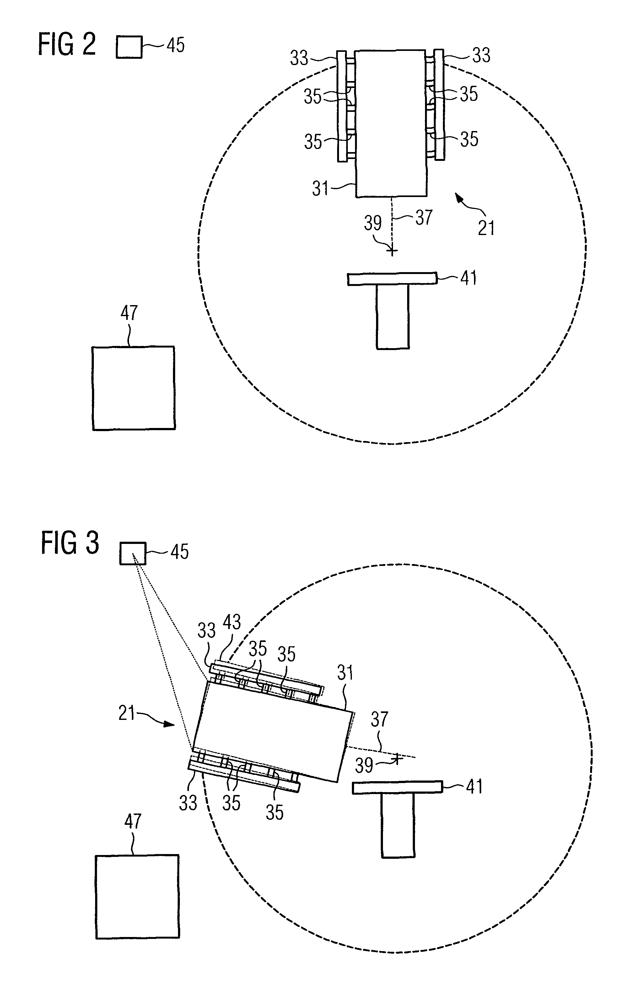
[0009]In one embodiment, a gantry for beam guidance of a particle beam includes at least one beam guidance element, a carrier device, and at least one moveable actuating element. The at least one beam guidance element b may guide the particle beam. The carrier device for the beam guidance element is rotatably mounted in such a way that by rotating the carrier device with the beam guidance element, the particle beam can be directed from various angles onto an object to be irradiated. The at least one moveable actuating element may adjust a spatial position of the beam guidance element.
[0010]A mechanical construction of the gantry can be considerably lighter and more cost-effective because a precise alignment of the at least one beam guidance element need no longer be guaranteed solely by the carrier device of the gantry or by an expensive commissioning of the gantry involving adjustment of the mounting elements. The spatial position of the beam guidance element can be adjusted within certain limits during operation of the gantry by the moveable actuating element of the gantry. Accordingly, the gantry structure, such as the carrier devices of the gantry, can be of a simpler, more cost-effective and space-saving design.
[0012]The spatial position of the beam guidance element can be adjusted by the moveable actuating element within certain limits during the operation of the gantry. Accordingly, the commissioning of a gantry may be sped up because expensive calibration procedures need to be carried out with less precision during the commissioning or servicing of the gantry. Compensation for a displacement of the building, for example, by foundation settling, is also possible within certain limits, without having to carry out a complete servicing or re-adjustment of the gantry. A variable deviation from a set position, for example, due to thermal expansion of mechanical parts, can be compensated for to a certain extent, such as during the operation of the gantry.
[0021]The measuring device may be fixed. In one embodiment, the measuring device can have at least one contactless laser measuring system, with which, for example, the position of suitable measuring points on the beam guidance element can be measured. The beam guidance element may be corrected within an accuracy range of 0.1 mm, for example, using fixed set positions. This guarantees a high degree of reliability during the operation of a gantry.

Problems solved by technology

A spatially precise guidance of the particle beam may be enabled by mechanically rigid gantry structures or expensive commissioning procedures, these are however associated with substantial costs and construction effort.
When the space around the object to be irradiated has to be freely accessible, a part of the gantry is usually attached to a cantilevered supporting structure, which makes the design of the mechanical structure of the gantry even more difficult.

Method used


Image

  • Gantry, particle therapy system, and method for operating a gantry
  • Gantry, particle therapy system, and method for operating a gantry
  • Gantry, particle therapy system, and method for operating a gantry

Examples


Embodiment Construction

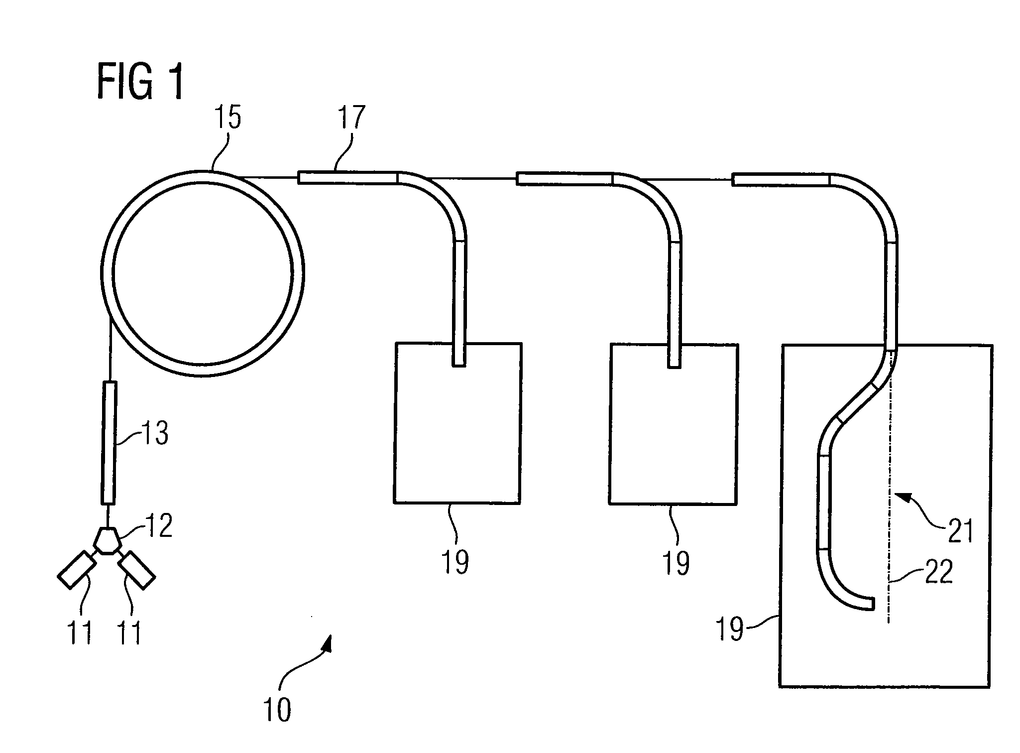
[0035]FIG. 1 shows a particle therapy system 10. The particle therapy system 10 may be used to irradiate a body, such as a tumor-diseased tissue, using a particle beam.

[0036]Ions, such as protons, pions, helium ions, carbon ions or other types of ions, may be used as the particles. The particles are generated in one or more particle sources 11. As shown in FIG. 1, two particle sources 11 are present that generate two different types of ion. Accordingly, switching can take place between both these types of ions within a short time interval. A switching magnet 12, for example, may be used for switching. The switching magnet 12 may be arranged between the ion sources 11 and an initial accelerator 13. For example, the particle therapy system 10 may be operated with either protons or carbon ions.

[0037]The ions generated from the one or more particle sources 11, and if appropriate also the ions selected by the switching magnet 12, are accelerated in the initial accelerator 13 to a first e...


PUM


Abstract

The present embodiments relate to a gantry for the beam guidance of a particle beam with at least one beam guidance element. A carrier device is rotatably mounted in such a way that the particle beam can be directed by a rotation of the carrier device with the beam guidance element from various angles on to an object to be irradiated. At least one moveable actuating element may adjust a spatial position of the beam guidance element.

Description

[0001]This patent document claims the benefit of German Patent Document DE 10 2007 050 168.6 filed on Oct. 19, 2007, which is hereby incorporated by reference.BACKGROUND[0002]The present embodiments relate to a gantry for beam guidance of a particle beam.[0003]Particle therapy is a method for the treatment of tissue, such as tumor diseases. Irradiation methods are, however, used in non-therapeutic areas. Non-therapeutic areas include, for example, research as part of particle therapy, which is carried out on non-living models or bodies, or irradiation of materials. Charged particles are accelerated to high energy and are formed into a particle beam and guided to one or more radiation rooms by means of a high-energy beam transport system. In the radiation room, the object to be irradiated is irradiated by the particle beam. “Fixed beam” radiation rooms direct the particle beam to an object to be irradiated from one or more fixed directions. Furthermore, gantry-based radiation rooms d...

Claims


Application Information

Patent Timeline
Patent Type & Authority Patents(United States)
IPC IPC(8): A61N5/10G21K1/093
CPCA61N5/10A61N5/1081A61N2005/1087
Inventor EMHOFER, STEPHANKAISER, WERNER
Owner SIEMENS HEALTHCARE GMBH
Learn More