
Device and method for measuring amounts of milk in particular during the milking process

Active Publication Date: 2011-08-09
GEA FARM TECH
View PDF19 Cites 4 Cited by
  • Summary
  • Abstract
  • Description
  • Claims
  • Application Information

AI Technical Summary

Benefits of technology

[0025]It is another significant advantage of the invention in all of the embodiments that continuous measuring is possible, not related to the number of analysis electrodes as is the case with a system according to DE 37 37 607 A1. Namely, the resolution capabilities of the known devices is reduced further with the measuring area not being utilized to the full. To achieve a satisfactory in-flow measuring accuracy, these devices must provide an adequately large flow-through height such that the measuring housing must be configured comparatively large or high enough. This is not required with the device according to the invention since the resolution generally is not related to the structural configuration of the electrodes. A device according to the invention can thus be optimally adjusted to the milk flow of a specific species (e.g. cows or ewes), so as to achieve optimal resolution for said species both for maximum milk flows and for minimum milk flows.
[0026]Preferably the measuring device is positioned in a measuring section that may be provided in a housing of the device. The housing preferably comprises at least one inlet and at least one outlet. Between the inlet and the outlet there is provided a measuring section in which the liquid to be measured is conveyed e.g. in a channel.
[0027]In measuring, the height of the flowing liquid is captured not in steps but continuously. Measuring accuracy can thus be enhanced.
[0028]According to the invention it is not the fill height that is measured but an integral density profile. Due to the principle applied, individual calibration for each cow or for the race of the cows is not required.
[0029]The mass flow is derived from the density profile. The calibration parameters used are those including the influences specific to the devices. For example one takes into account which flow velocity will ensue from which density profile.
[0030]The response time of the device is determined by the response time of the electronic analysis components which generally allows fast milk flow measuring.

Problems solved by technology

One problem encountered in milk flow measuring is that milk is a heavily foaming fluid.
The considerable proportion of air in the air-fluid mixtures to be discharged may thus cause not only individual foam bubbles but substantial formation of foam which considerably impairs in-flow milk yield measurement.
Since the proportion of foam does not readily permit conclusions on mass from the volume, the accuracy of milk yield measuring methods through volumetric methods has its limits.
Another problem in measuring the milk yield flow is caused by the periodic milk flow.
Determining the actual milk flow is difficult under these conditions.
Due to these influences, measuring a milk flow is found to be difficult since the nature and composition of the foam phase on the one hand and on the other hand also the composition and quality of the liquid phase within one milking process and between milking processes are subject to fluctuations.
Owing to the principle, however, periodically operating measuring methods do not allow precise determination of the current milk flow in particular with slight milk flows.
One drawback of optical measuring is for example that small and large foam bubbles may scatter the light beam employed for measuring such that in the presence of a foam portion, not enough light can be measured in transmission or reflection measuring so as to result in measuring errors.
Given a distance of e.g. 1.5 mm, this may mean a measuring error of nearly 1.5 mm, which with slight milk flows at low fill heights of a few millimeters may result in correspondingly large measuring errors.
Due to this principle, this known device is very complex in terms of mechanics and electronics since a large number of electrodes must be installed and individually selected electrically.
It is another disadvantage that despite the high number of employed electrodes the milk flow is only evaluated in steps, thus causing inaccuracies.
It is therefore still a major challenge to integrate a sensor in the milk flow offering satisfactory measuring accuracy at a reasonable price for farmers.

Method used


Image

  • Device and method for measuring amounts of milk in particular during the milking process
  • Device and method for measuring amounts of milk in particular during the milking process
  • Device and method for measuring amounts of milk in particular during the milking process

Examples


Embodiment Construction

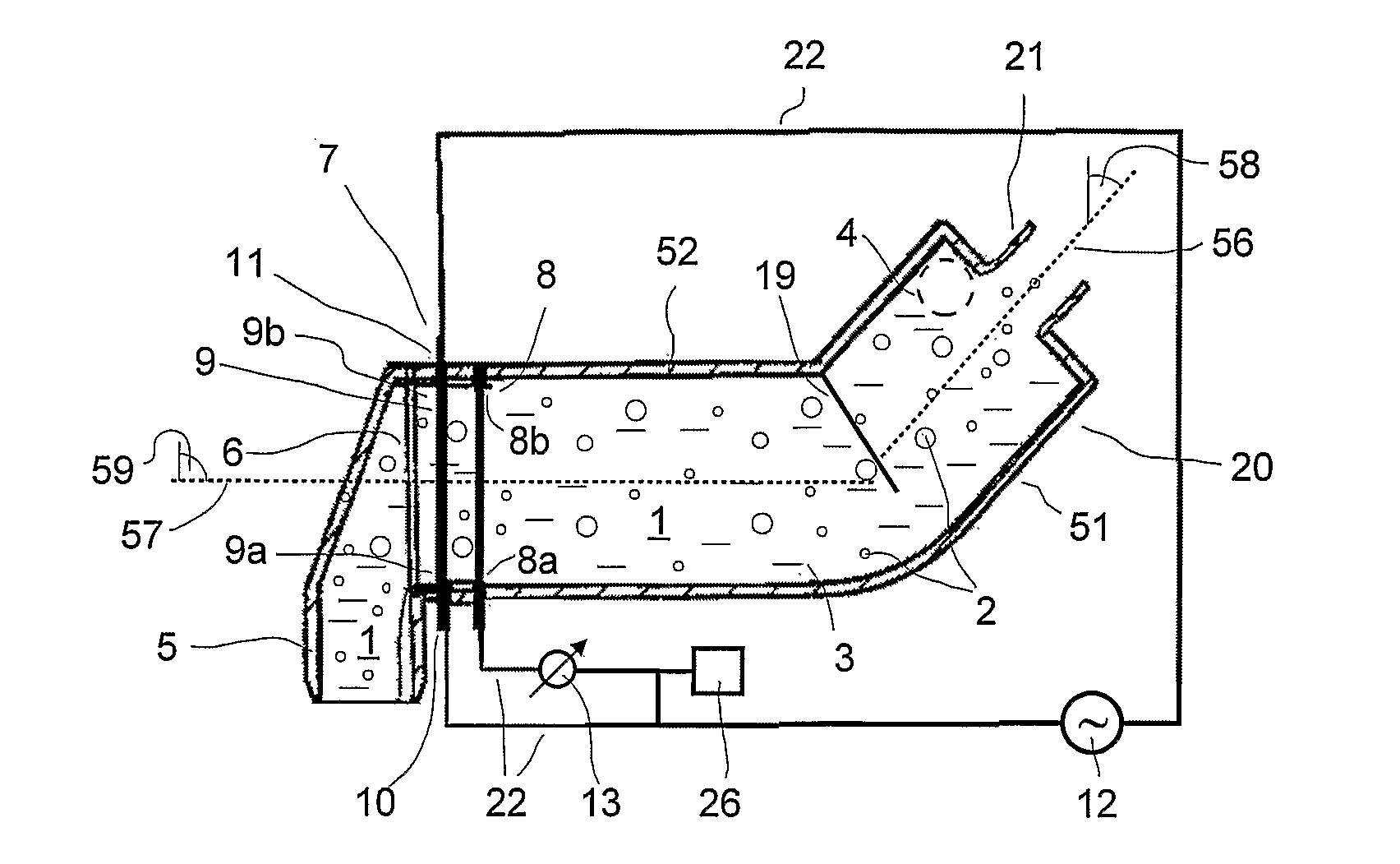
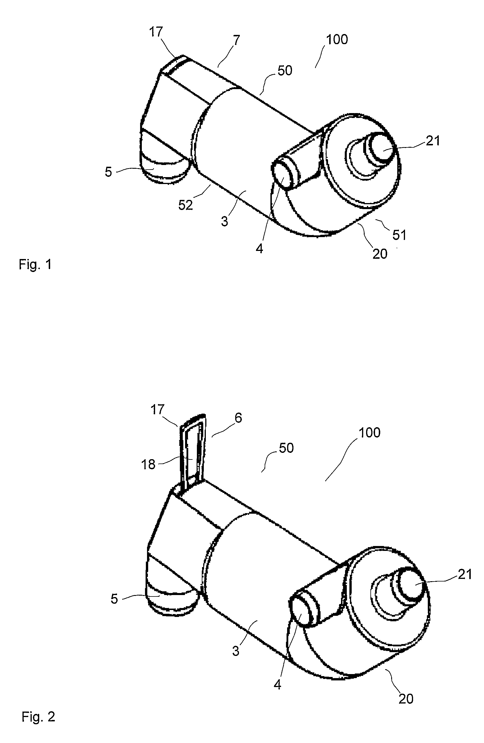
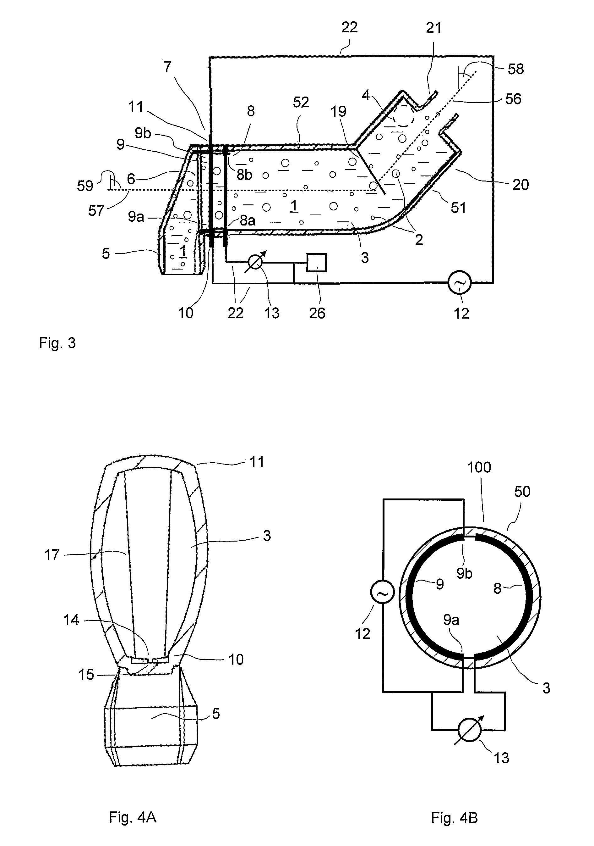
[0144]The FIGS. 1 and 2 show a first embodiment of a device 100 according to the invention in a perspective view for measuring a mass flow of a fluid 1, in particular a foam containing or foamy liquid or a foaming liquid such as milk. In the vicinity of the inlet 4 of the housing 50 a pressure compensation nozzle 21 is provided to remove air. The inlet 4 leads tangentially into the housing 50 such that the fluid rotates while running into the housing. Furthermore a channel 3 is provided subsequent to the inlet 4.

[0145]A measuring system 7 is positioned in the channel 3 in front of a diaphragm 17 in this embodiment with said diaphragm 17 being positioned upstream in front of a drain 5. The diaphragm 17 serves as a flow resistance 6 (see FIG. 2). Preferred embodiments provide that the diaphragm can be inserted (see FIG. 1) or exchanged (see FIG. 2) as needed. Exchanging the diaphragm 17 allows to adjust the flow resistance to different conditions since e.g. in milking ewes or goats th...


PUM


Abstract

The invention relates to a device for measuring the mass flow, in particular of a foaming liquid, comprising a measuring device with two electrodes and at least one electrical means for generation of an electrical parameter and an analytical device. The electrical means is connected to the first electrode at two remote points, such as to be wired in parallel with the first electrode. The second electrode is connected to the first electrode by means of the analytical device.

Description

FIELD AND BACKGROUND OF THE INVENTION[0001]The invention relates to a device and a method for measuring the amounts of milk in particular during the milking process. The invention is generally suitable for determining the quantity of milk yield from cows, ewes, goats, buffaloes, llamas, camels, dromedaries, or of other lactating mammals and will be described below with reference to the milking of e.g. cows.[0002]In addition the invention may be used in other areas of application where the measuring of quantities or mass flows of foamy or foam-forming liquids is concerned such as measuring the mass flow of beers, soft drinks, fruit juices, or other similar food products, as well as foaming or foamy technical fluids, such as electroplating solutions.[0003]Information about the current milk flow is important for controlling the milking process so as to adjust parameters during milking e.g. for specifying the transition from the stimulating phase to the main milking phase, or the remova...

Claims


Application Information

Patent Timeline
IPC IPC(8): G01F1/56
CPCA01J5/01G01F1/56
Inventor SPRINGER, ANDREASKRONE, OTTO
Owner GEA FARM TECH
Learn More