Motor polygon assembly (MPA) facet reflectivity mapping

a technology of facet reflectivity and motor polygons, applied in the field of image data processing, can solve the problems of lack of effective control of output intensity and manufacturing errors, and achieve the effects of minimizing overall setup, minimizing mpa output reflectivity, and improving outpu

Inactive Publication Date: 2011-08-09
XEROX CORP
View PDF15 Cites 7 Cited by
  • Summary
  • Abstract
  • Description
  • Claims
  • Application Information

AI Technical Summary

Benefits of technology

[0009]It is, therefore, one aspect of the present invention to provide for an improved image data processing.
[0010]It is another aspect of the present invention to provide for improved system performance in using a raster output scanner.
[0011]It is a further aspect of the present invention to provide a solution that minimizes motor polygon assembly (MPA) output reflectivity differences by real time facet reflectivity measurement and mapping.
[0013]This present solution minimizes MPA output reflectivity by real time facet reflectivity measurement and mapping. The polygon facets are set setup with the help of the motor polygon assembly. A automatic power control (APC) sensor looks at the beam of the laser during over scan periods ‘outside’ of printing time. Errors are recorded internal to the ROS to minimize overall setup in image output terminal (IOT) manufacturing. The graphical output when analyzed from the processing of this method gives better output. The percentage of rise in the digitized signal can be analyzed with the rotation of the polygon facets.

Problems solved by technology

Usually in motor polygon assembly (MPA), errors may occur during manufacturing.
Based upon these errors erratic beam reflectivity may occur from each facet in a ROS Imager MPA assembly that is then passed on to ROS outputs as dysfunctions in critical applications.
The present inventor has recognized a drawback of prior art of laser scanning is with lack in effectively controlling the output intensity variation of exposing beam(s) of a rotating polygon type image forming apparatus using control marks formed on a rotating surface portion of a polygon member or a motor polygon assembly.

Method used


Image

  • Motor polygon assembly (MPA) facet reflectivity mapping
  • Motor polygon assembly (MPA) facet reflectivity mapping
  • Motor polygon assembly (MPA) facet reflectivity mapping

Examples


Embodiment Construction

[0020]The particular values and configurations discussed in these non-limiting examples can be varied and are cited merely to illustrate at least one embodiment and are not intended to limit the scope thereof.

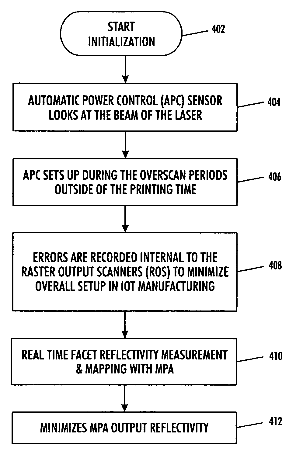
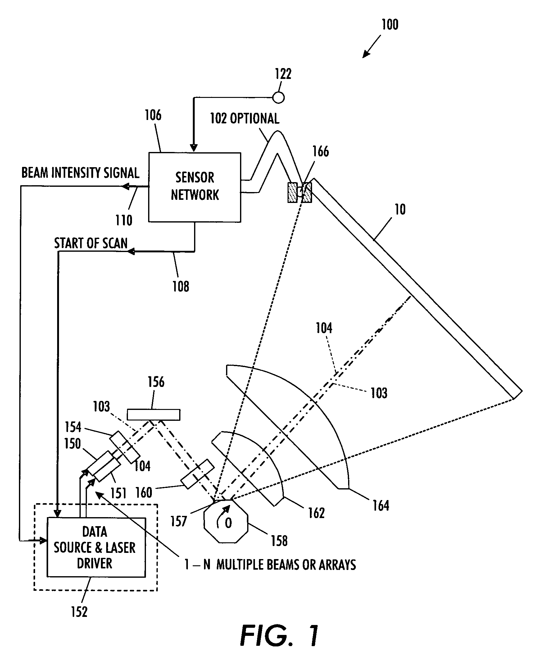
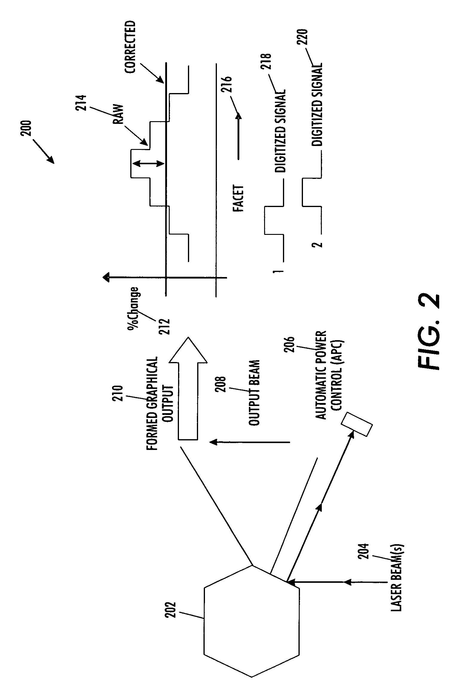
[0021]Referring to FIG. 2, illustrated is a perspective view 200 with the formed graphical analysis of the method adopted with motor polygon assembly (MPA) facet reflectivity mapping, which can be implemented in accordance with a preferred embodiment. A rotating polygon mirror 202 is kept adjacent to its facets, in which the laser beam is transmitted. The rotating polygon is configured with the help of the polygon motor driver and the response is generated to the automatic power control (APC) 206. The laser beam 204 is sent to the facets of the rotating polygon. The output beam 208 is configured and sent with the help of the automatic power control (APC). During the process the formed graphical output 210 is shown. The percentage of change 212 is analyzed in the vertical axis o...


PUM


Abstract

A technique for minimizing motor polygon assembly output reflectivity using real time facet reflectivity measurements and mapping. An automatic power control sensor manages laser beams produced by the laser source associated with the system during overscan periods ‘outside’ of defined printing time. Errors are then recorded internal to the raster output scanner to minimize overall setup in the image output terminal.

Description

TECHNICAL FIELD[0001]Embodiments are generally related to image data processing. Embodiments are also related to the field of laser scanning. Embodiments are additionally related to minimizing MPA output reflectivity variation by real-time facet reflectivity measurement and mapping.BACKGROUND OF THE INVENTION[0002]Processes and devices used for electro photographic printers wherein a laser scan line is projected onto a photoconductive surface are known. In the case of laser printers, facsimile machines, and the like, it is common to employ a raster output scanner (ROS) as a source of signals to be imaged on a pre-charged photoreceptor (a photosensitive plate, belt, or drum) for purposes of xerographic printing. The ROS provides a laser beam which switches on and off as it moves, or scans, across a photoreceptor.[0003]Commonly, the surface of the photoreceptor is selectively imaged and discharged by the laser in locations to be printed. On-and-off control of the beam to create the de...

Claims


Application Information

Patent Timeline
Patent Type & Authority Patents(United States)
IPC IPC(8): B41J27/00
CPCB41J2/471
Inventor PEPE, MARTIN
Owner XEROX CORP
Why Eureka
Try Eureka