Film cooling hole for turbine airfoil

a technology of air cooling hole and turbine, which is applied in the direction of engine fuction, machine/engine, engine manufacturing, etc., can solve the problems of reducing the efficiency of film cooling hole, so as to achieve less turbulence

Inactive Publication Date: 2011-08-16
SIEMENS ENERGY INC
View PDF3 Cites 330 Cited by
  • Summary
  • Abstract
  • Description
  • Claims
  • Application Information

AI Technical Summary

Benefits of technology

[0007]It is an object of the present invention to provide for a film cool...

Problems solved by technology

Some of the cooling are is ejected directly into the mainstream flow and causes turbulence, coolant dilution and a loss of downstream film effectiveness.
Also, the hole breakout in the streamwise elliptical shape will induce stress problems in a blade applic...

Method used


Image

  • Film cooling hole for turbine airfoil
  • Film cooling hole for turbine airfoil
  • Film cooling hole for turbine airfoil

Examples


first embodiment

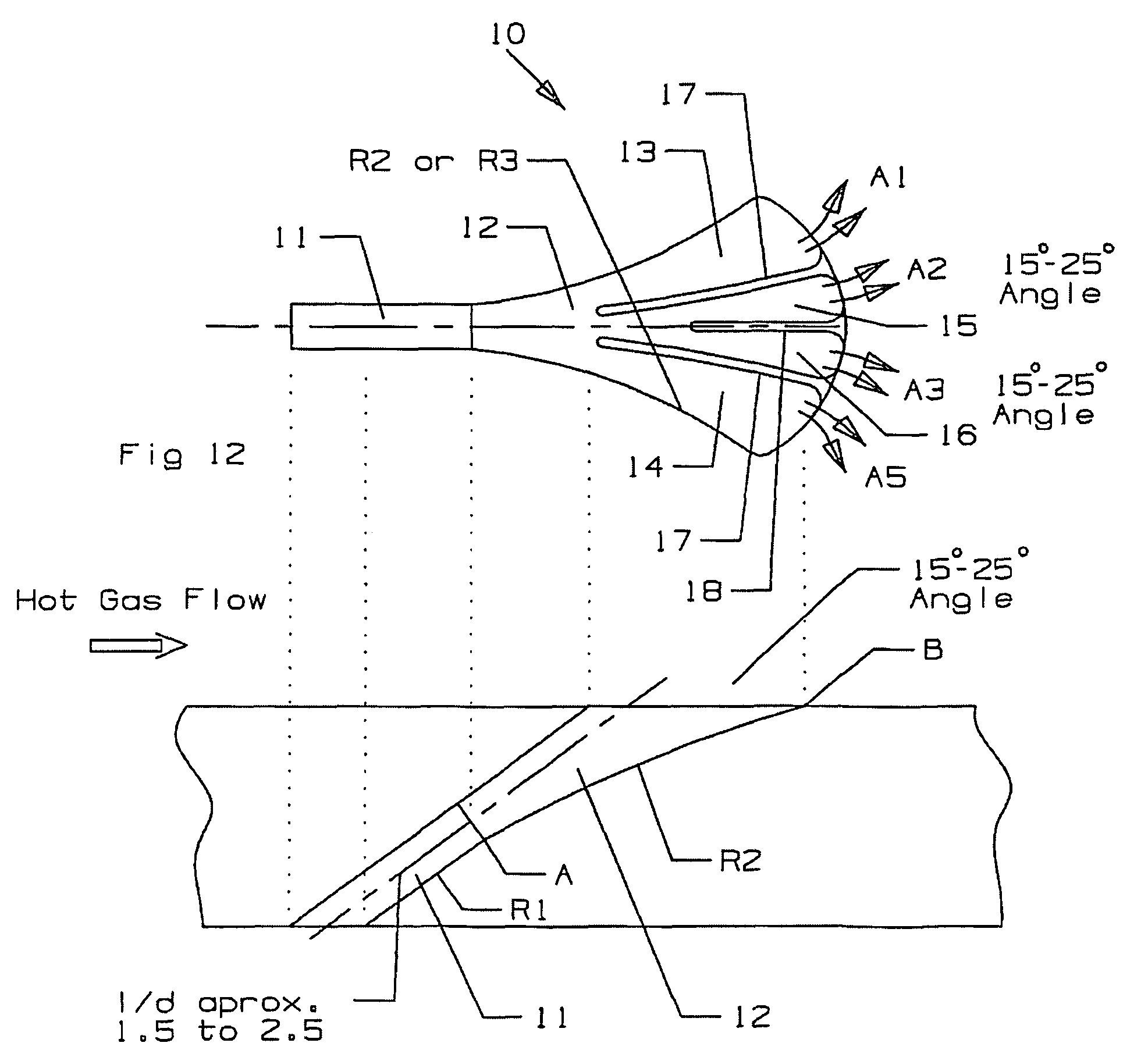
[0028]The film cooling holes of the present invention are shown in FIGS. 12 through 15 where the first embodiment is shown in FIGS. 12 and 13. FIG. 12 shows the film cooling hole 10 with an inlet metering section 11 having a constant diameter and a diffusion section 12 located immediately downstream in the flow direction of the cooling air. The diffusion section 12 in this particular embodiment includes four separate passages formed by three flow guides. Two outer flow guides 17 form two outer diffusion passages 13 and 14 with the two side walls of the diffusion passage 12. An inner flow guide 18 forms two inner diffusion passages 15 and 16 with the two outer flow guides 17.

[0029]The inlet section 11 has a constant diameter along the length to provide for metering of the pressurized cooling air through the film hole 10. The downstream wall is shown in FIG. 13 to have a radius of curvature R1, but this curvature is infinite since this surface is flat and parallel to the upper wall su...

second embodiment

[0032]FIGS. 14 and 15 show the film cooling hole in which the film hole is a compound angled film hole. FIG. 12 shows a top view of the film hole with the same basic shape as in the FIG. 12 film hole except the film hole is angled with respect to the hot gas flow path over the film hole. The left side wall has a 0 to 5 degree expansion while the right side wall has a radius of curvature of R3. Two outer ribs form three inlets to the diffusion section of the film hole, and two inner ribs of shorter length form three separate diffusion paths inside of the two outer ribs. The total angle of the film hole outlet is from 20 to 30 degrees which is the compound angle of the film hole. FIG. 13 shows a cross section side view of the film hole with the metering inlet section of constant diameter area followed by the diffusion section that has a downstream wall with a radius of curvature of R2 and an outlet angle of 1.5 to 25 degrees.

[0033]In the FIG. 12 embodiment, each individual inner wall ...


PUM


Abstract

A turbine airfoil with a film cooling hole having a bell mouth shaped opening that has expansion in both the side walls and the downstream wall of from 15 to 25 degrees. The film cooling hole includes an expansion section formed with two long ribs and one short rib to form three inlets of equal cross sectional areas so that the flows into the three passages are the same. The short rib forms two middle passages to combine with two outer passages to form four exit passages for the film hole. The two side walls are curved outward in the stream-wise oriented film hole and have an expansion of from 0 to 5 degrees in the compound angled film hole.

Description

FEDERAL RESEARCH STATEMENT[0001]None.CROSS-REFERENCE TO RELATED APPLICATIONS[0002]None.BACKGROUND OF THE INVENTIONField of the Invention[0003]The present invention relates generally to a gas turbine engine, and more specifically to an air cooled airfoil in the engine.Description of the Related Art including information disclosed under 37 CFR 1.97 and 1.98[0004]Airfoils used in a gas turbine engine, such as rotor blades and stator vanes (guide nozzles), require film cooling of the external surface where the hottest gas flow temperatures are found. The airfoil leading edge region is exposed to the highest gas flow temperature and therefore film cooling holes are used here. Film cooling holes discharge pressurized cooling air onto the airfoil surface as a layer that forms a blanket to protect the metal surface from the hot gas flow. The prior art is full of complex film hole shapes that are designed to maximize the film coverage on the airfoil surface while minimizing loses.[0005]Stand...

Claims


Application Information

Patent Timeline
IPC IPC(8): F01D5/08
CPCF01D5/186F05D2250/121F05D2250/292F05D2250/71F05D2260/202F05D2250/20
Inventor LIANG, GEORGE
Owner SIEMENS ENERGY INC
Why Eureka
Try Eureka