
Diffuser for an aeration system

a diffuser and aeration system technology, applied in the direction of combustible gas purification/modification, heating types, separation processes, etc., can solve the problems of limited slit size and high density of diffuser slits, and achieve the effect of increasing the dissolved gas concentration in the water pool, enhancing the oxygen transfer coefficient and standard oxygen transfer ra

Active Publication Date: 2011-08-23
KANG NA HSIUNG ENTERPRISE CO LTD
View PDF22 Cites 4 Cited by
  • Summary
  • Abstract
  • Description
  • Claims
  • Application Information

AI Technical Summary

Benefits of technology

The present invention provides a diffuser for an aeration system that improves the transfer of oxygen in water. The diffuser includes a base, a valve member, and a diaphragm. The diaphragm is designed to move the valve member to a non-aerating position when the inlet is closed and to an aerating position when the back pressure is higher than the ambient pressure. The diaphragm has a base web layer and a porous foam layer with fibrous filaments and pores to enhance the transfer of oxygen. The technical effect of this invention is to increase the dissolved gas concentration in a water pool.

Problems solved by technology

However, since the elastomeric material is tough, limits are encountered with respect to how small the slits can be made and to how high the density of the slits of the elastomeric membrane diffuser can be provided.

Method used


Image

  • Diffuser for an aeration system
  • Diffuser for an aeration system
  • Diffuser for an aeration system

Examples


Embodiment Construction

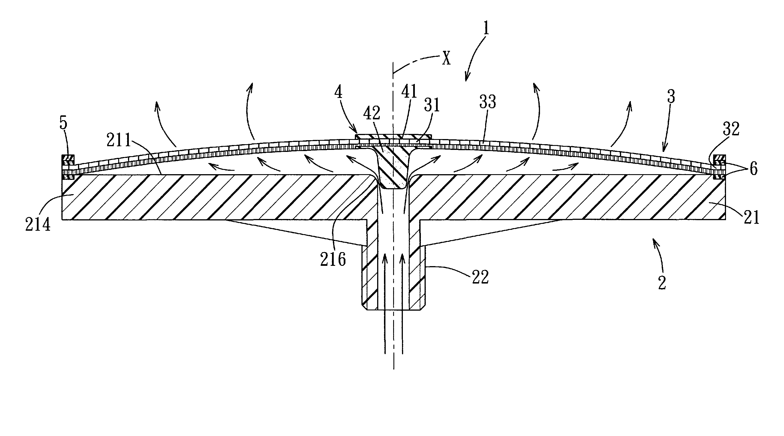
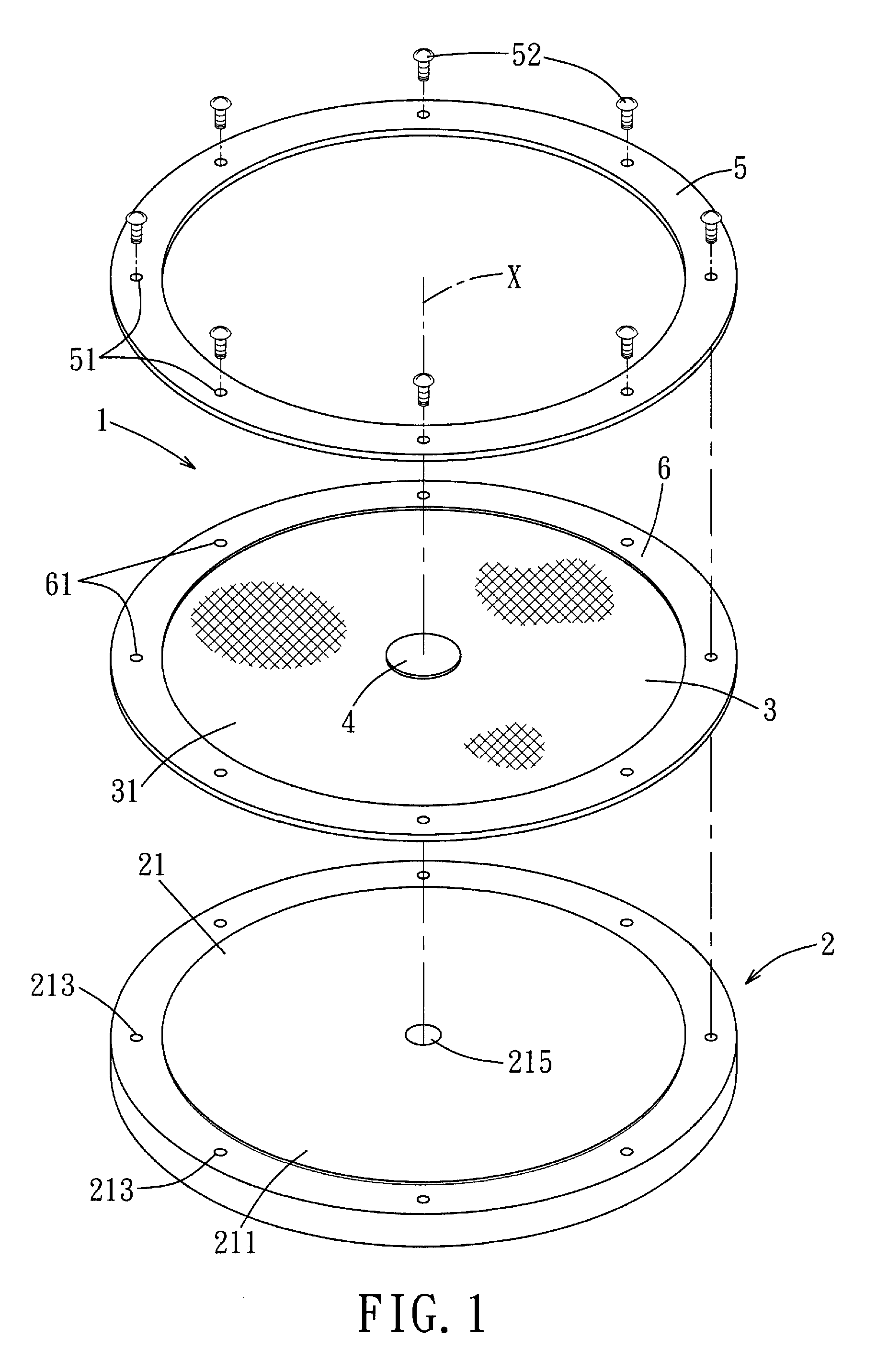
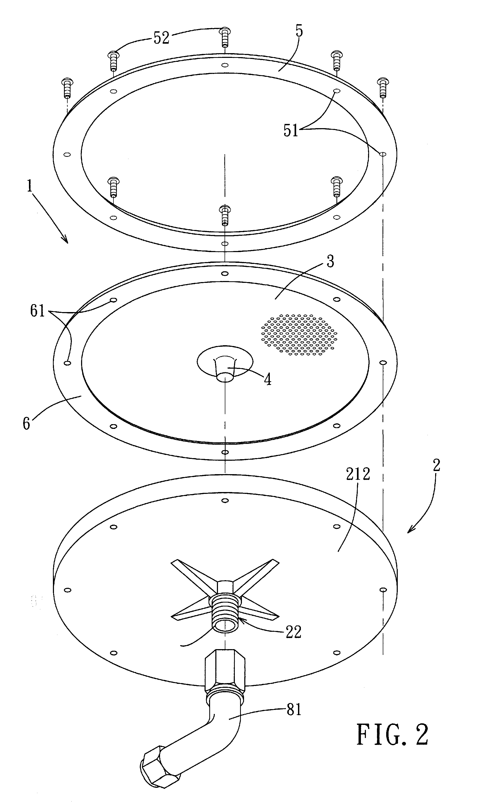
Referring to FIGS. 1, 2, 3, and 4, the first embodiment of a diffuser 1 for an aeration system according to this invention includes a base 2, a valve member 4, and a diaphragm 3.

The base 2 has a major wall 21 with a periphery 214, and defines a central line (X) that is normal to the major wall 21. The major wall 21 has an outer major surface 211 and an inner major surface 212 opposite to the outer major surface 211, and defines an inlet 215 that is adapted to introduce thereinto an aerating gas from the aeration system to generate a back pressure and that extends along the central line (X) through the outer major surface 211 to form thereon a valve seat 216. The base 2 may further have a conduit portion 22 which extends from the inner major surface 212 along the central line (X) and which is in fluid communication with the inlet 215 for the introduction of an aerating gas from a conduit 81 of the aeration system into the inlet 215. In order to allow the diffuser 1 to be easily repla...


PUM

PropertyMeasurementUnit
elongation at breakaaaaaaaaaa
sizeaaaaaaaaaa
sizeaaaaaaaaaa

Abstract

A diffuser for an aeration system includes a base, a valve member, and a diaphragm. The diaphragm has a central portion, a peripheral portion, and a surrounding segment. The surrounding segment is interposed between the central portion and the peripheral portion, and includes a base web layer and a porous foam layer. The base web layer includes a plurality of fibrous filaments arranged to form a textured structure with a plurality of pores. The porous foam layer is disposed on the base web layer.

Description

BACKGROUND OF THE INVENTION1. Field of the InventionThe invention relates to a diffuser for an aeration system, and more particularly to a diffuser which allows gas introduced in the aeration system to form small and fine bubbles, so as to increase the concentration of a gas, such as oxygen, that is dissolved in a water pool equipped with the aeration system.2. Description of the Related ArtIn order to establish an aerobic condition commonly used in the treatment of wastewater or sewage, or in the cultivation of biological materials in water pools, an aeration system is employed to increase the oxygen concentration in water.An aeration system includes a plurality of diffusers adapted to be provided on the bottom of a water pool, conduits connected to the plurality of diffusers, and a blower forcing air to flow into the conduits and to pass through the slits provided in the diffusers, so as form bubbles in the water pool.A conventional diffuser disclosed in, for example, U.S. Pat. No...

Claims


Application Information

Patent Timeline
Patent Type & Authority Patents(United States)
IPC IPC(8): B01F3/04
CPCB01F3/04269B01F2003/04276B01F2003/04297B01F2003/0439B01F23/23125B01F23/231262B01F23/23124B01F23/231243
Inventor HU, YEN-JUNGPAN, HUANG-CHIN
Owner KANG NA HSIUNG ENTERPRISE CO LTD
Learn More