
Corner piece for valance interface in cases and containers

a technology of valance interface and corner piece, which is applied in the direction of valance connection, container, tray container, etc., can solve the problems of compromising the integrity of the container, endangering the contents within, and the valance frame system used in conjunction with continuous valance frames in containers with tight radius corners lacking substantial flexural strength and lateral shear resistan

Active Publication Date: 2011-08-23
IMPACT CASES
View PDF44 Cites 4 Cited by
  • Summary
  • Abstract
  • Description
  • Claims
  • Application Information

AI Technical Summary

Benefits of technology

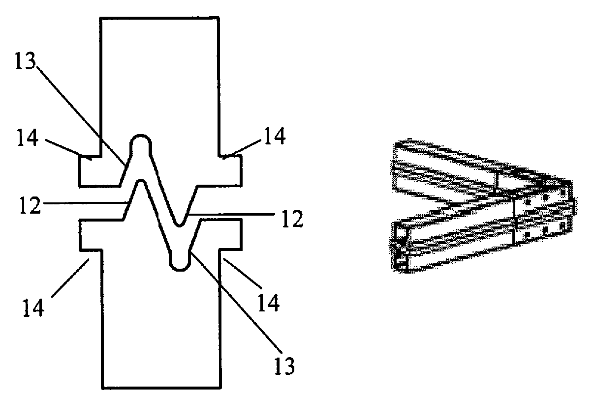
[0038]According to one aspect of the invention, a bent corner piece for a valance frame has a shaped valance interface surface that extends continually around the face of the bend and an extending tongue at each of the two ends of the corner piece, each tongue being shaped to interfit and engage, preferably intimately, with a recess formed in the end of an adjacent, preferably extruded, longitudinal frame member carrying an aligned valance along one side. Complementary corner pieces so formed can provide part of a valance interface between the lid and body of a container as examples of two objects being mated, ensuring sealing continuity around corners fitted with such corner pieces as well as along the longitudinal frame members.
[0045]A corner piece may have a groove along its shaped mating valance surface which engages with a ridge on a complementary corner piece, and vice versa. Alternately, the mating valance surface of the corner piece may have both a groove and a ridge formed therein with the complementary corner piece similarly having a groove and ridge of complementary shape and location. When such complementary corner pieces inter-fit, the valance interface is formed. In this way, a pair of corner pieces each will have mating valance surfaces each of a shape that will provide an intimate engagement with the mating valance surface of the other corner piece, the ridge(s) of one corner piece engaging the groove(s) on the other corner piece and vice versa.
[0048]The groove of a corner piece is intended to be aligned with the groove formed in an adjacent longitudinal frame member. The recess in the end or core of such adjacent frame member, particularly if the frame member is fabricated by extrusion, may be shaped to provide room for the groove to be present in the frame member. A deep groove in the frame member may intrude into the hollow core of the longitudinal frame members, reducing the shape and size of the recess at its ends. In such case the tongue at each end of the corner piece may be shaped with a cross-sectional shape other than in the form of a rectangle. Such tongues may be provided with a tongue groove formed along the lengths of such tongue to engage with a frame member recess that is shaped to accommodate the presence of a frame member groove.
[0049]A corner piece preferably is formed with a plurality of cavities underlying the valance surface of the corner piece wherein such cavities are defined by a one or more bridging walls extending from an insidewall of the corner piece to an outside wall of the corner piece. Each cavity may then be provided with one or more perforated fastener openings penetrating the outside wall of the corner piece for attaching sidewalls of a container to the corner piece. These perforated fastener openings provide for a robust attachment of the external sidewall of the container to the corner pieces. Such a firm attachment is highly desirable in order to maintain the alignment of the corner pieces.
[0052]In addition to a valance frame subassembly's complementary ridge and groove arrangement, each subassembly should preferably possess a supplementary, shoulder profile which comes into contact with the adjacent edge of a container side wall panel. This assists in ensuring that the valance frame subassembly is fixed in a consistent position along the edge of the wall panel of the base or lid segment of the case to which it is attached. This shoulder profile may be in the shape of a protruding rectangular shoulder formed on the longitudinal frame members and on the corner pieces. This profile on each corner piece functions by overlying the attached edge of the adjacent sidewall panel in order to improve the alignment of the subassembly.

Problems solved by technology

Any lateral movement produced at these boundaries will compromise the integrity of the container and potentially endanger the contents within.
The existing valance frame system used in conjunction with continuous valance frames in a container having tight radius corners often lacks substantial flexural strength and lateral shear resistance because the cross-sectional profile of such frames must be thin and simple enough to facilitate bending of the valance frame sub-section around the radius of the corner.
Further, eliminating or minimizing the gap distance is difficult to achieve on a consistent, repeatable basis.
There is no teaching, however, of a corner piece in this patent.

Method used


Image

  • Corner piece for valance interface in cases and containers
  • Corner piece for valance interface in cases and containers
  • Corner piece for valance interface in cases and containers

Examples


Embodiment Construction

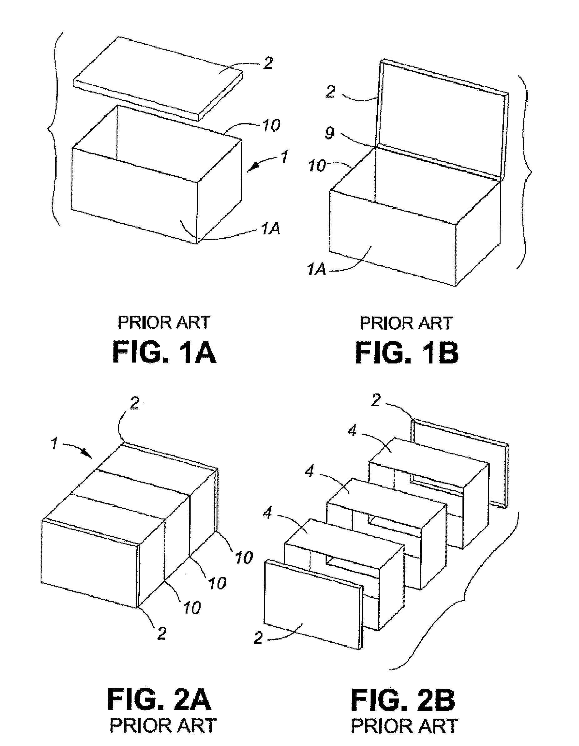
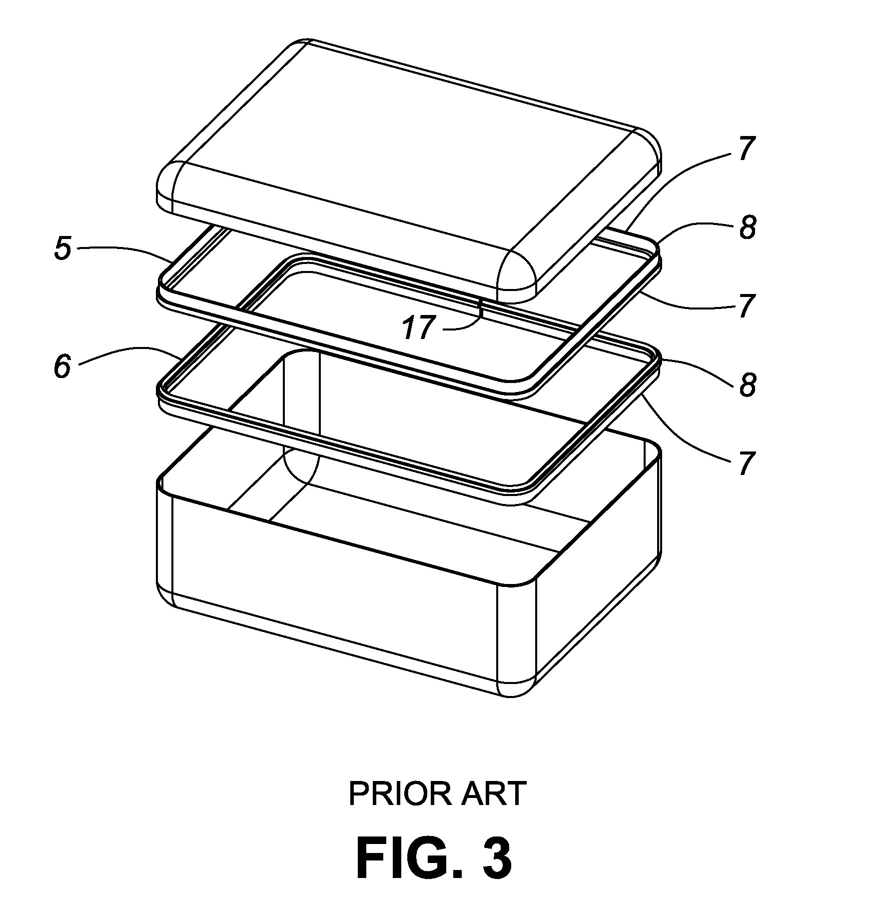
[0069]FIGS. 1 to 3 depict various sealable containers known in the art. FIGS. 1A and 1B illustrate a container 1 with a lid 2 and an open-faced bottom portion 1A. The lid 2 and bottom portion 1A may either be connected through a hinge means 9, as in FIG. 1B, or they may remain disjointed, as in FIG. 1A. FIGS. 2 and 2A describe a variant of this embodiment, in which a container comprises multiple base segments 4 each having two opposing, open regions and two enclosing lids 2, as depicted in FIG. 2B. The multiple base segments 4 are positioned sequentially, with valance interfaces 10 between each two base segments 4, forming an elongated container 1 as depicted in FIG. 2A. Again, two lids 2 are aligned to enclose the open ends of the container 1. In every instance, the dimensions of the lid and base combinations are such that they sufficiently complement each other so as to enclose a volume within the container 1.

[0070]According to another prior art configuration, at the boundary betw...


PUM


Abstract

A unitary, bent corner piece for a valance frame has an extending tongue at each end shaped to interfit the hollow cross-section of an adjacent, extruded, valance frame member. Complementary corner pieces so formed provide part of a valance interface between the lid and body of a container, ensuring sealing continuity around corners fitted with such corner pieces. Each corner piece is provided with a mating valance surface for presentation to the valance interface to provide an intimate engagement with the mating valance surface of the complementary, opposed corner piece. Gaskets fitted within the corner pieces may form part of the interface. Tongues formed a at the respective ends of a corner piece are provided with a groove to accommodate the inclusion of a gasket into the interior core of the longitudinal frame members. Corner pieces may also be formed with two or more cavities beneath the valance surface, such cavities being defined by bridging walls extending from an inside surface of the corner piece to an outside surface of the corner piece. The outside surface of a corner piece may be provided with one or more perforated fastener openings, penetrating the outside wall of the corner piece, for attaching sidewalls of a container to the corner piece.

Description

[0001]This application claims the benefit of U.S. Provisional Patent Application No. 60 / 867,643 with a filing date of Nov. 29, 2006.FIELD OF THE INVENTION[0002]This invention relates to sealable cases and containers. More particularly, it relates to a corner piece along the closure or valance interface of a case or container having a lid. The invention also applies wherever two objects mate along a valance interface.BACKGROUND TO THE INVENTION[0003]Valuable and / or fragile objects often require storage or transportation in protective cases or containers. Typically, cases or containers which accommodate these objects are designed to be sturdy and strong. Although many different styles of containers exist, three primary designs are as follows, wherein the description is with respect to the figures described further below.[0004]The first case style makes use a single base 1 and a single lid 2 is shown in FIG. 1A. An interior frame system (not shown) is typically located along the closur...

Claims


Application Information

Patent Timeline
Patent Type & Authority Patents(United States)
IPC IPC(8): B65D6/00
CPCB65D7/44B65D15/22B65D21/08Y10T403/4602Y10T403/345Y10T403/349
Inventor HAMLEN, JAMES GREGORY
Owner IMPACT CASES
Learn More