Eureka AIR delivers breakthrough ideas for toughest innovation challenges, trusted by R&D personnel around the world.

Composite of aerogel and phase change material

a phase change material and aerogel technology, applied in the direction of thermal insulation protection of pipes, metallic materials, coating processes, etc., can solve the problems of aerogels that aerogels are difficult to apply to surfaces that require protection, and the thermal performance of binder materials is less attractiv

Active Publication Date: 2011-08-23
THE BOEING CO
View PDF23 Cites 14 Cited by
  • Summary
  • Abstract
  • Description
  • Claims
  • Application Information

AI Technical Summary

Benefits of technology

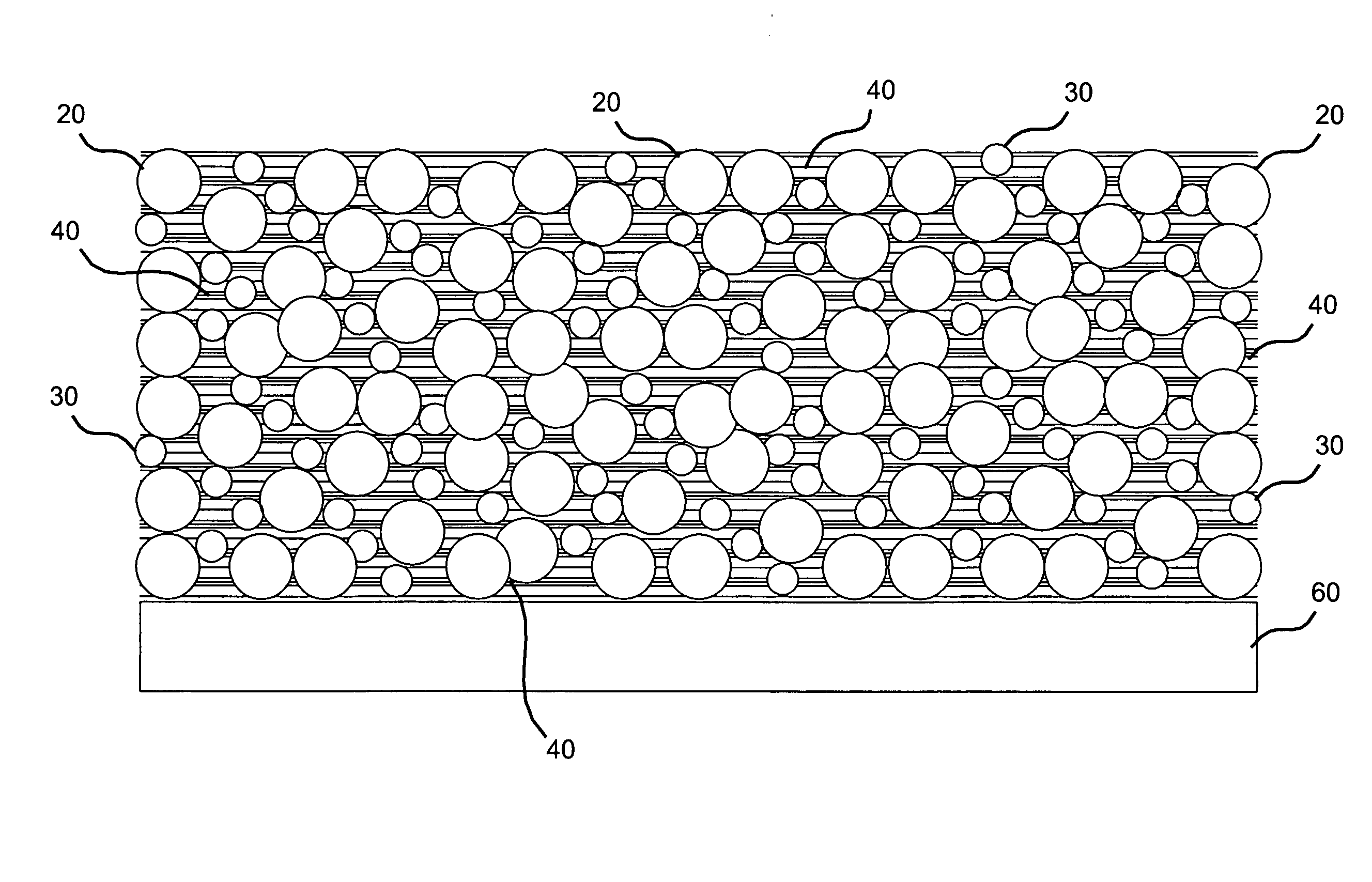
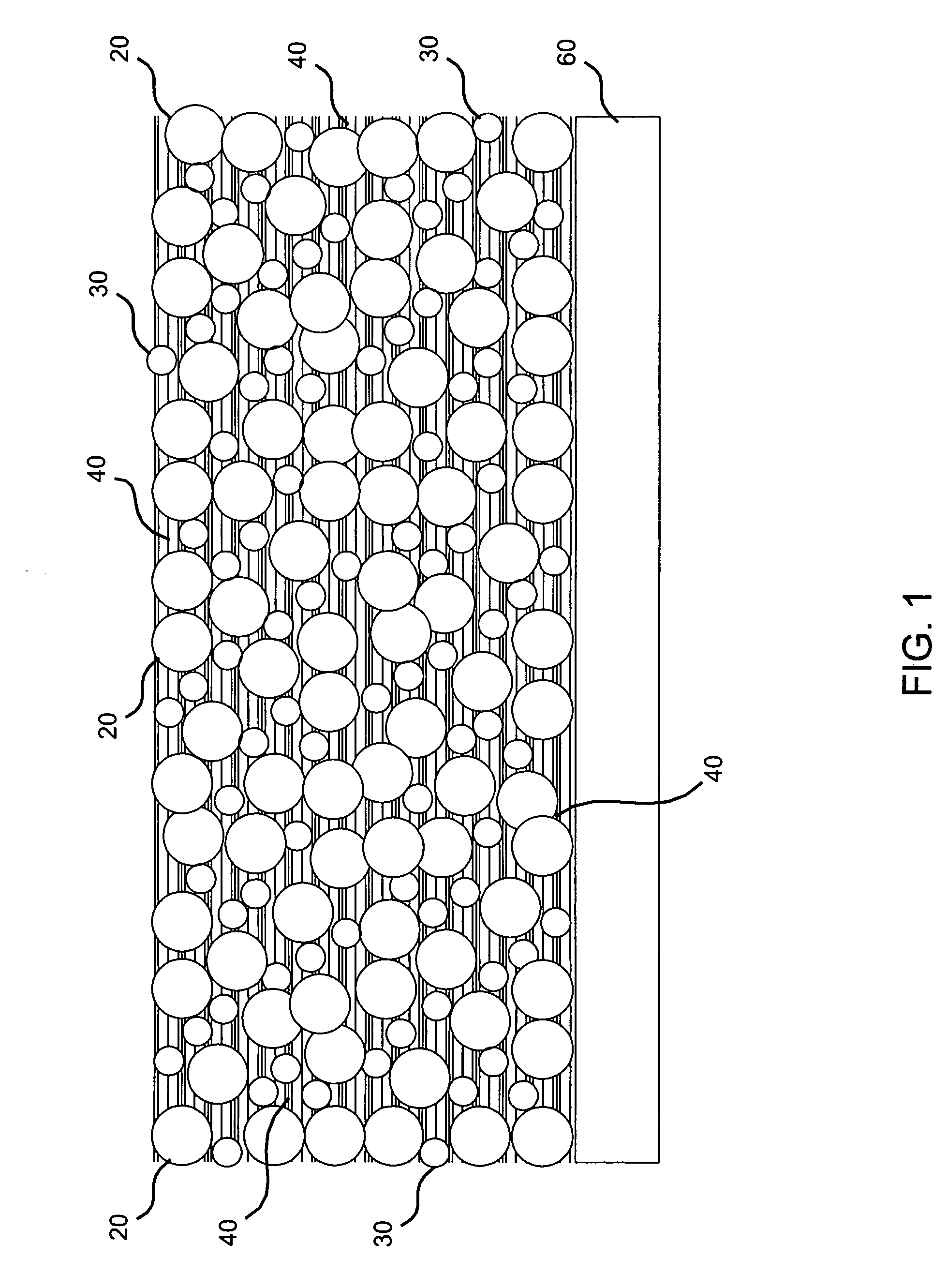
In summary, the present invention provides the advantage of use of a phase change material with aerogel in order to provide capability of absorbing heat while holding a constant temperature, thus effectively improving the thermal performance of the insulating body. The PCMs are used to at least temporarily maintain a maximum temperature. Therefore, adding the PCM to the aerogel composite provides the advantage of the transient thermal performance of the aerogel along with the heat absorbing capability of the PCM, thereby providing better thermal protection than with the aerogel material alone. Preliminary tests as shown herein have demonstrated good thermal performance coupled with a delay in the heat transport through the coating. The results as contained herein show advantageous thermal conductivity and delay of transient heat transfer of the composites of the invention. The aerogels provide the advantage of low steady state thermal conductivity. The binder matrix retains the particles of materials and the PCM material provides delay of the transient heat transfer effects.

Problems solved by technology

This is particularly the case where vehicles experience severe heat loads for extended periods of time.
Unfortunately, aerogels are difficult to apply to surfaces that require protection.
Aerogels are available in solid or, more usually, flexible blanket forms and are not conventionally sprayed.
However, the binder material has less attractive thermal performance as compared to the aerogel; consequently, substitution of a portion of the aerogel for the binder presents a disadvantage.

Method used


Image

  • Composite of aerogel and phase change material
  • Composite of aerogel and phase change material
  • Composite of aerogel and phase change material

Examples


example

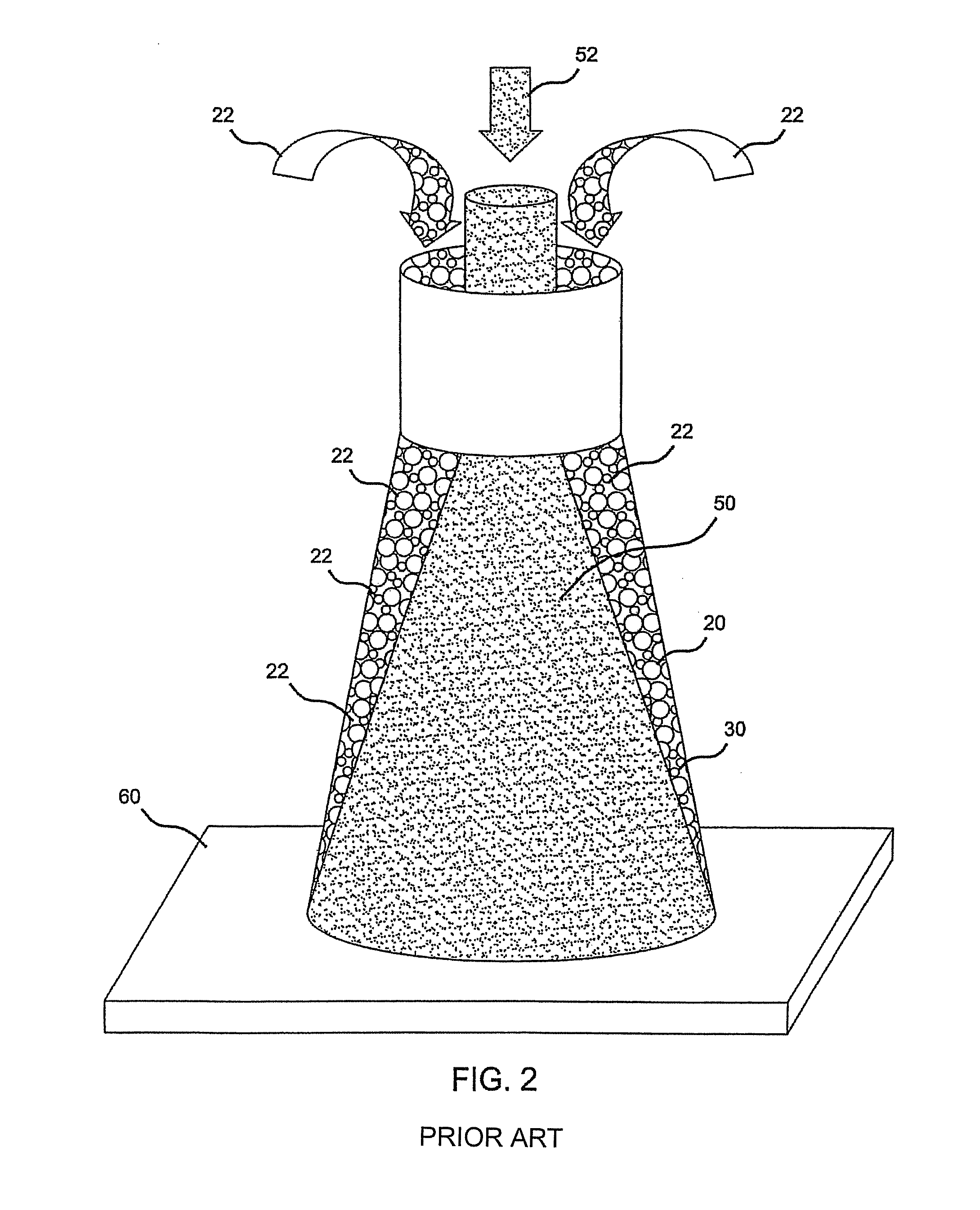
Deposition of the silicone matrix binder 40, aerogel 20 and PCM 30 material were accomplished by an apparatus as schematically shown in FIG. 2 for application onto a substrate. The preferred process was a convergent spray process. By the convergent spray process, aerogel particles 20 become mixed with the liquid silicone precursor 50 immediately prior to or at deposition on the substrate 60.

PCM beads are also included and they may be included in either the silicone mixture 50 or along with the aerogel 20 or separately. Thus, two or more deposition streams may be utilized. The method of deposition minimizes breakup of the friable aerogel particles and minimizes absorption of a solvent by the particles. Any conventional spraying apparatus may be utilized to achieve the formation of the deposition streams. Preferred deposition rates are shown in Table 1 along with exemplary compositions of the deposition material.

Table 1 also includes the results of the thermal analysis showing the the...


PUM

PropertyMeasurementUnit
temperatureaaaaaaaaaa
diameteraaaaaaaaaa
particle sizesaaaaaaaaaa

Abstract

A method of forming a thermally insulating body that may involve co-depositing onto a substrate, particles containing aerogel material, particles containing phase change material, and a solution containing a binder and a carrier. The phase change material may have encapsulated phase change material particles in which a phase change substance encapsulated within durable capsules transitions from a solid to a liquid at a temperature greater than about 100 degrees Fahrenheit. The carrier may be removed after the co-deposition to form a solid thermally insulating body on the substrate.

Description

FIELD OF THE INVENTIONThis invention pertains to aerogels and to thermal insulation composites containing aerogel.BACKGROUND OF THE INVENTIONAerogels are known to provide good thermal insulation properties and have attractive thermal protection per unit weight as compared to other materials. Materials with high thermal insulation such as aerogels are required for ever-increasing speed utilized in vehicles, particularly aircraft. This is particularly the case where vehicles experience severe heat loads for extended periods of time. Unfortunately, aerogels are difficult to apply to surfaces that require protection. Aerogels are available in solid or, more usually, flexible blanket forms and are not conventionally sprayed. Neither the solid or blanket form is as readily applied to a surface as a sprayed material. Aerogels can be applied by a spray application process wherein aerogel-binder compositions are used for application of the aerogel, where the binder holds the aerogel particle...

Claims


Application Information

Patent Timeline
Patent Type & Authority Patents(United States)
IPC IPC(8): B29C67/00
CPCC04B20/10C04B26/32F16L59/028C04B14/064C04B20/008C04B24/38C04B40/0028C04B2111/00146C04B2111/28Y02E60/14
Inventor LAWTON, STANLEY A.
Owner THE BOEING CO
Why Eureka
Eureka Blog
Learn More