AI technical title is built by PatSnap AI team. It summarizes the technical point description of the patent document.
a technology for information devices and cooling systems, which is applied in the direction of electrical apparatus casings/cabinets/drawers, semiconductor/solid-state device details, electrical apparatus casings/cabinets/drawers, etc., can solve the problems of large amount of electric power and large amount of heat, and the temperature of the servers cannot be lowered, so as to reduce the number of fan units and reduce the power supply to the fan
Active Publication Date: 2011-08-23
FUJI FURUKAWA ENG & CONSTR +1
View PDF31 Cites 66 Cited by
Summary
Abstract
Description
Claims
Application Information
AI Technical Summary
This helps you quickly interpret patents by identifying the three key elements:
Problems solved by technology
Method used
Benefits of technology
Benefits of technology
The invention is a server-cooling system that improves cooling for heat-generating servers in an air-conditioned room. It includes a rack system with cooling coils and fans, a shell for housing the rack system and cooling coils, and a one-way air flow to efficiently cool multiple racks in a smaller space. The system reduces the need for auxiliary fan units and allows for a cooling structure to be built between racks using a reduced number of fan units. The system also expels air from the shell without affecting the room temperature.
Problems solved by technology
However, such blade type servers are large in processing power, and therefore consume a large amount of electric power and generate a large amount of heat.
However, in cases where the density of heat generated by servers is larger, the temperature of the servers cannot be lowered only by cooling air, which is supplied from an air conditioner positioned near a wall of the room, from under the floor to cooling aisles, and hot spots occur at unexpected places.
Hence, a conventional cooling system which cools a whole room has not been able to cool a device with a high heat generation density.
The size of the duct areas is large, which poses a problem that the number of racks which can be placed in an air-conditioned room is reduced.
Method used
Image
Click on the blue label to locate the original text in one second.
Reading with bidirectional positioning of images and text.
Examples
Embodiment Construction
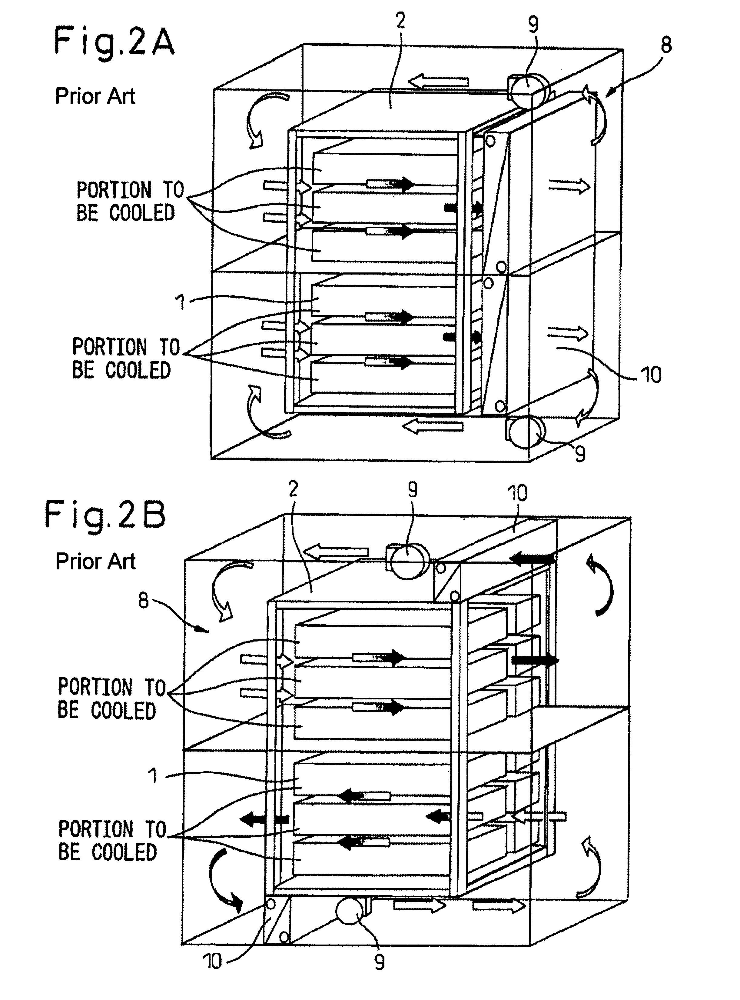
Before describing the preferred embodiments, an explanation will be given of a conventional cooling system for information devices shown in FIGS. 1A to 2B.
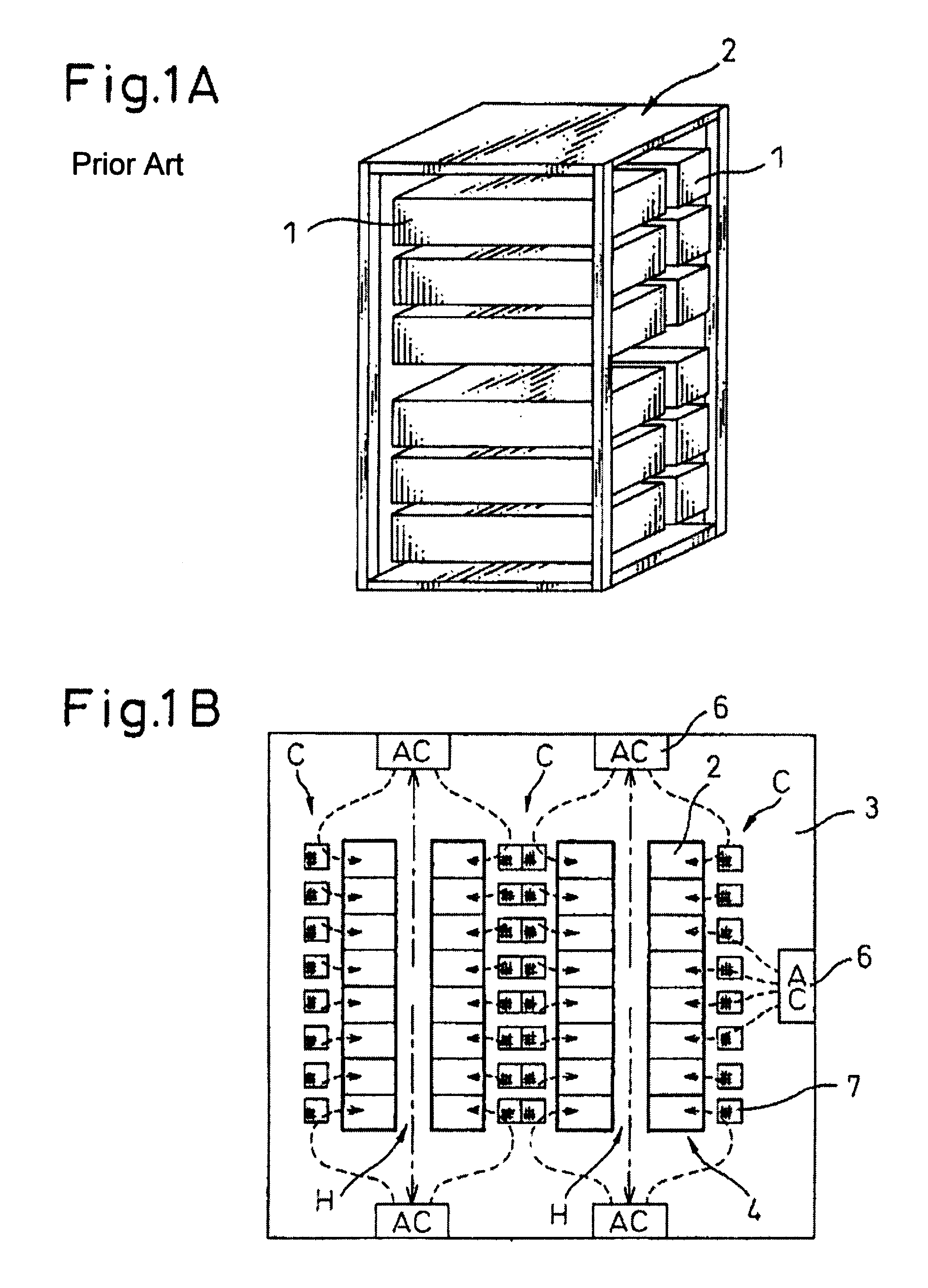
FIG. 1A shows a rack with cases stacked in two rows, in which blade type servers are housed in each case. The blade type server rack has a height of about 2 meters. In a data center or the like, a number of such racks are arrayed in positions in an air-conditioned room 3 dedicated to blade type servers, as shown in FIG. 1B. The air-conditioned room 3 needs to be cooled to prevent the temperature from rising because almost all of electric power supplied to the racks generates heat.
In the air-conditioned room 3, rack rows 4 each composed of racks 2 arrayed in a lateral direction are prepared. Further, the rack rows 4 are arrayed in rows in parallel, and warm air passages H and cooling aisles C are formed alternately between the rack rows 4. Conventional cooling of racks 2 in such air-conditioned room 3 is as follows: cooling air flo...
PUM
Abstract
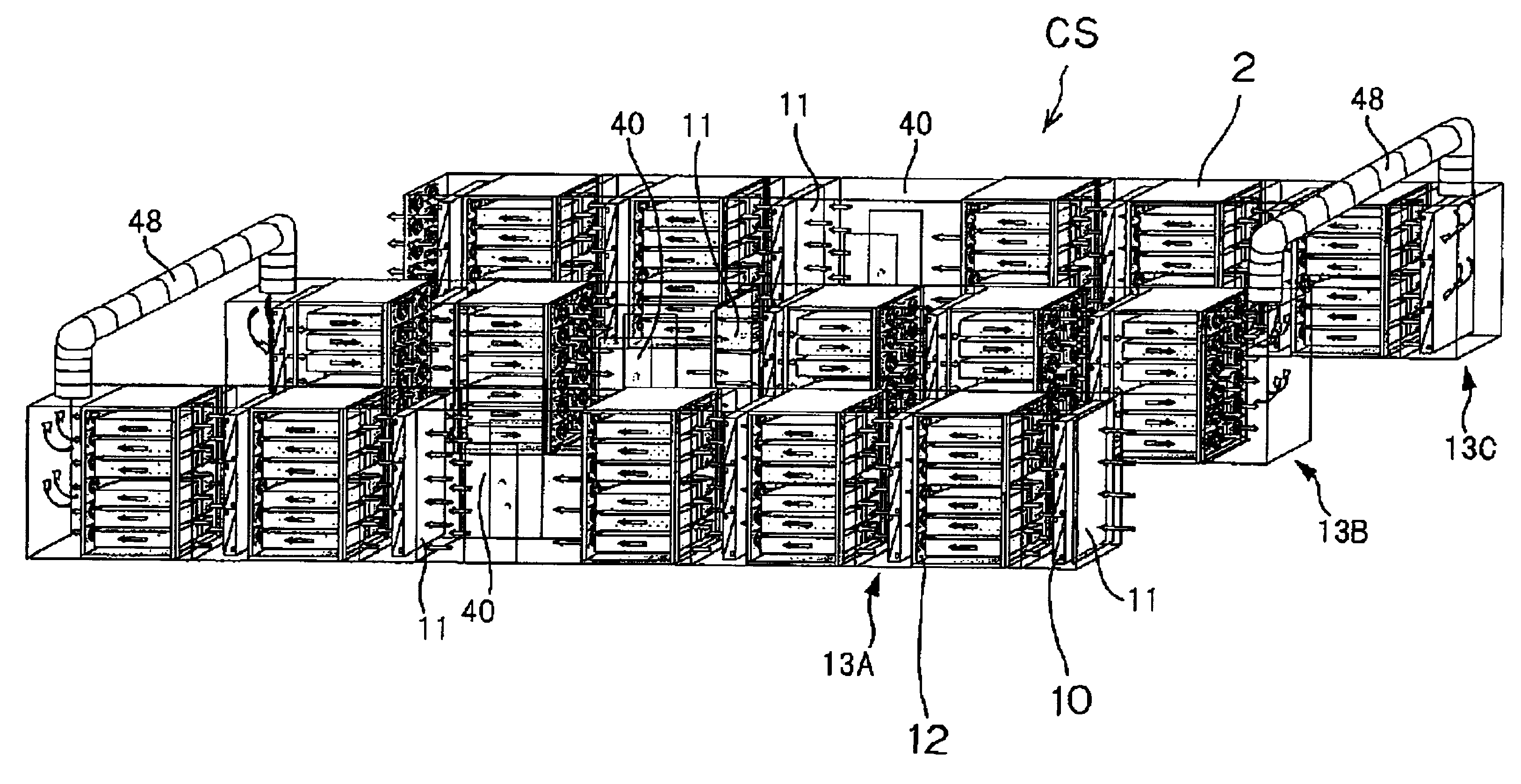
To cool a blade type server disposed in an air-conditioned room, the following arrangements are made. The first is at least one shell having a ventilation passage disposed in the air-conditioned room. The second is, the following are disposed in a ventilation passage: racks, in which blade type servers each composed of a case with slim boards housed therein are stacked; cooling coils each having a coolant passage and a cooling fin and cooling a passing air; and at least one fan unit having axial-flow fans placed therein and producing air currents in one direction. The third is the fan unit forces a cooling air to flow in one direction in the ventilation passage thereby to cool the servers in the racks. The cooling coils and racks are disposed alternately so that warmed cooling air after passing through the rack is cooled by the cooling coil and then cools the next rack.
Description
CROSS-REFERENCE TO RELATED APPLICATIONThis application claims priority from, and incorporates by reference the entire disclosure of Japanese Patent Application No. 2007-74810, filed on Mar. 22, 2007.BACKGROUND OF THE INVENTION1. Field of the InventionThe present invention relates to a cooling system for an information device, and more specifically a cooling system for preventing an information device used in a data center, a server room, etc., from thermally running out of control due to overheating.2. Description of the Related ArtConventionally, a number of servers as information devices are placed in e.g. a company's server room, a data center where an information device such as a computer is used to perform data calculation, data summarization, etc. In a room where a server is used, an air-conditioning device keeps the room temperature at a certain fixed value in order to prevent the server from thermally running out of control due to overheating. For a conventional server-cooli...
Claims
Application Information
Patent Timeline
Application Date:The date an application was filed.
Publication Date:The date a patent or application was officially published.
First Publication Date:The earliest publication date of a patent with the same application number.
Issue Date:Publication date of the patent grant document.
PCT Entry Date:The Entry date of PCT National Phase.
Estimated Expiry Date:The statutory expiry date of a patent right according to the Patent Law, and it is the longest term of protection that the patent right can achieve without the termination of the patent right due to other reasons(Term extension factor has been taken into account ).
Invalid Date:Actual expiry date is based on effective date or publication date of legal transaction data of invalid patent.

