Device and method for applying rotary tacks

a technology of rotary tacks and devices, applied in the direction of surgical staples, surgical forceps, manufacturing tools, etc., to achieve the effect of convenient use and manipulation, and easy entry

Inactive Publication Date: 2011-08-30
EASYLAP LTD
View PDF27 Cites 1191 Cited by
  • Summary
  • Abstract
  • Description
  • Claims
  • Application Information

AI Technical Summary

Benefits of technology

[0006]The present invention seeks to provide devices and methods for applying surgical fasteners, such as rotary tacks, to tissues, such as for hernia repairs and the like, as is described more in detail hereinbelow. The device, herein referred to as a tacker, has a drive shaft with articulates with an applicator arm. Rotation of the drive shaft causes rotation of the articulated applicator arm and causes rotation of rotary tacks disposed in a magazine at the distal end of the articulated applicator arm, thereby screwing the tacks into tissue. The articulated applicator arm of the tacker pivots with respect to the drive shaft, thereby permitting the surgeon access to hard-to-reach places. The tacker of the invention pivots the articulated applicator arm and applies the rotary tacks all in one single, smooth squeeze of the trigger. Thus the tacker is very user-friendly for surgeons and can easily be used and manipulated with one hand, thereby freeing the other hand for other tasks. The tacker is dimensioned (e.g., 5 mm overall diameter for each of the drive shaft, articulated applicator arm and magazine housings) for easy entry into a trocar and the like.

Problems solved by technology

However, Shipp does not have a joint in the device, that is, the device has a long shaft with no bending or pivoting in the shaft.
This is a disadvantage when trying to reach areas with difficult access thereto.

Method used


Image

  • Device and method for applying rotary tacks
  • Device and method for applying rotary tacks
  • Device and method for applying rotary tacks

Examples


Embodiment Construction

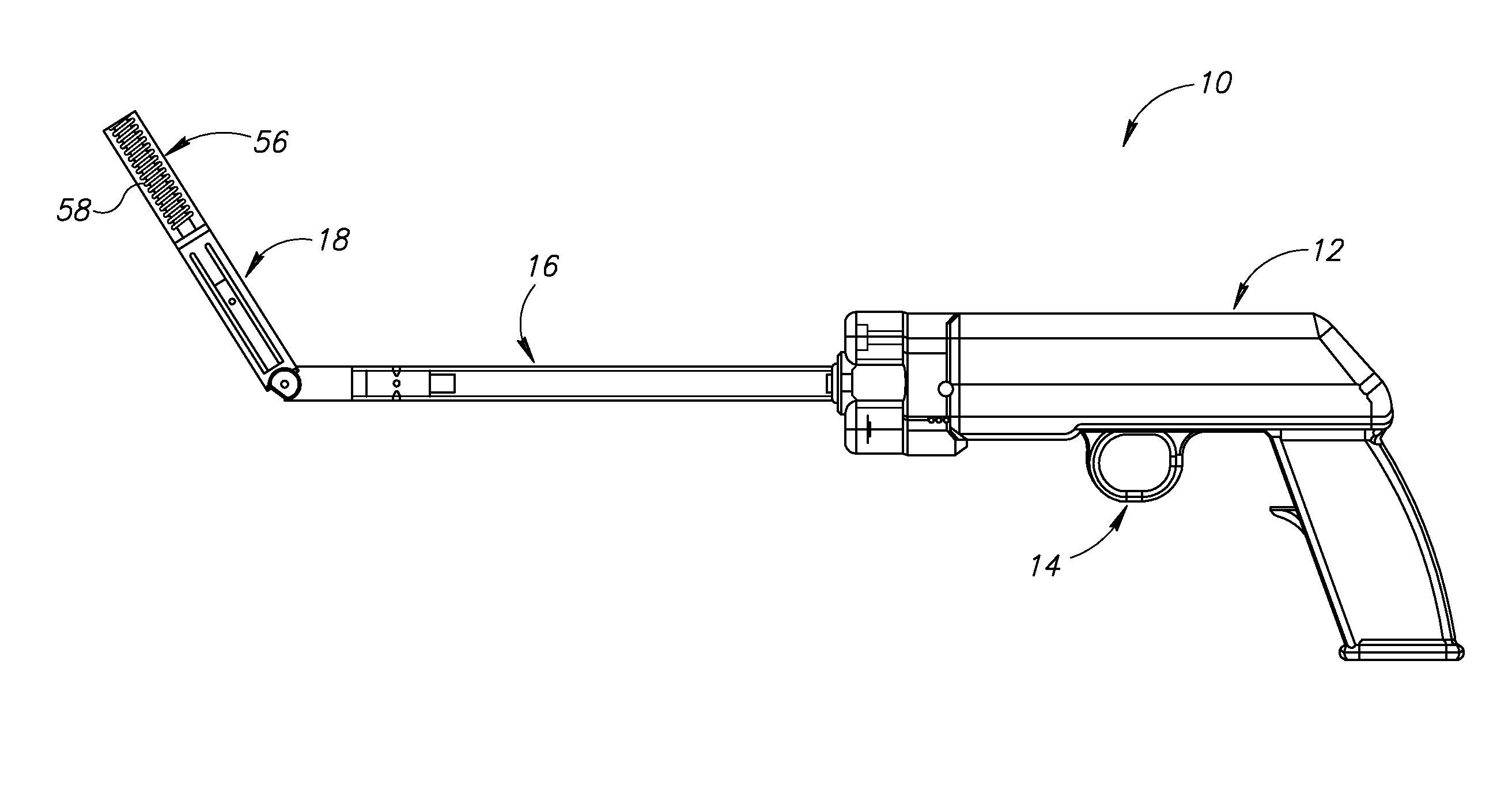
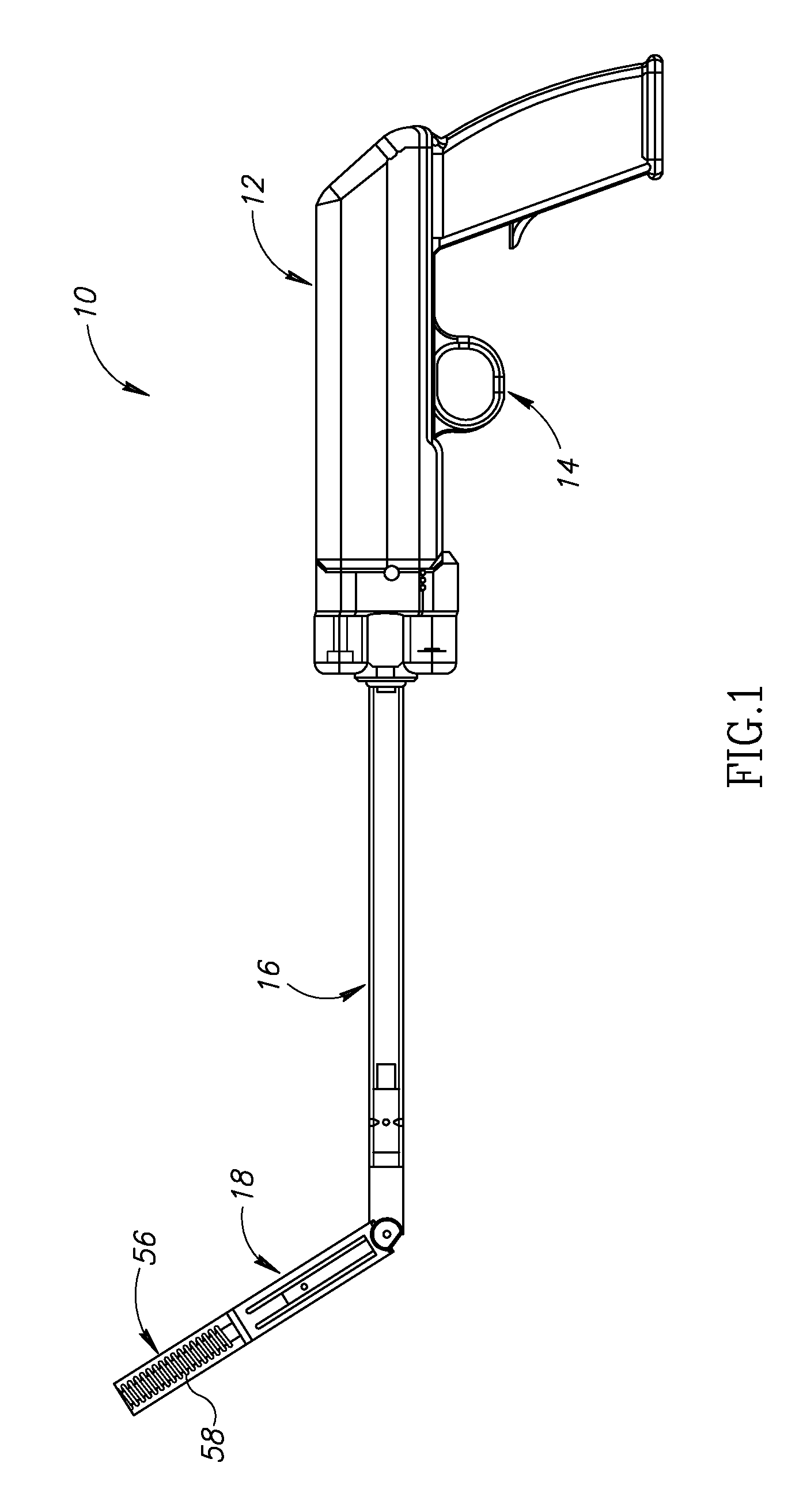
[0027]Reference is now made to FIG. 1, which illustrates a tacker 10, constructed and operative in accordance with an embodiment of the present invention.

[0028]Tacker 10 may include a handle 12 with a trigger assembly 14, described further in detail hereinbelow with reference to FIG. 8. A drive shaft 16 is coupled to trigger assembly 14. An articulated applicator arm 18, described more in detail hereinbelow with reference to FIGS. 5-7, is pivotally connected to drive shaft 16.

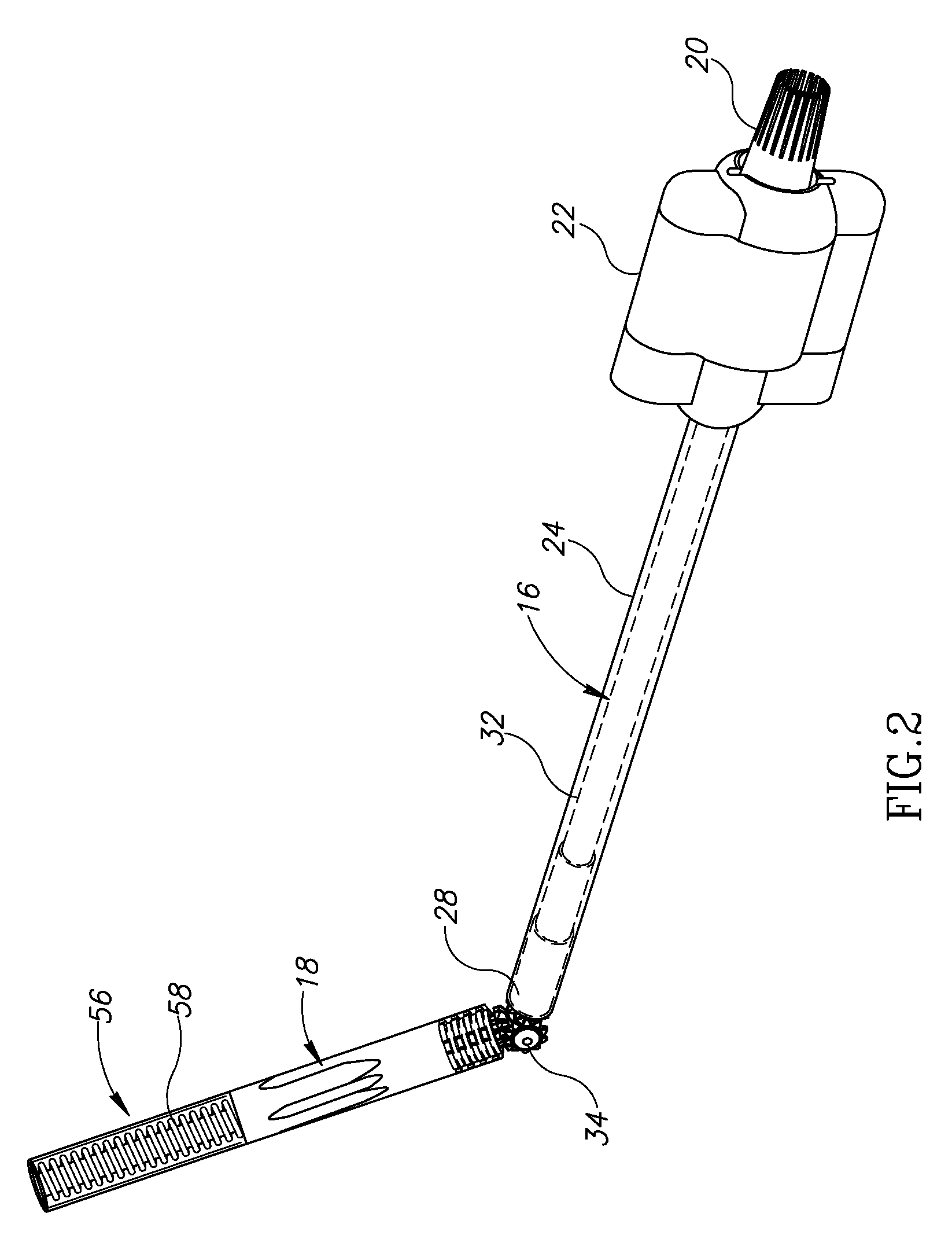
[0029]Reference is now made to FIGS. 2, 3, 6 and 7. A proximal end 20 of drive shaft 16 is splined (or otherwise suitably shaped) for mating with trigger assembly 14 (the mating connection being described further hereinbelow with reference to FIG. 8). The proximal end 20 of drive shaft 16 is journaled in a roller bearing housing 22 (FIG. 2). Drive shaft 16 extends through an extension tube (also called housing) 24 and a drive gear 26 is attached to a distal end 28 of drive shaft 16 (FIGS. 6 and 7). The distal e...


PUM

PropertyMeasurementUnit
diameteraaaaaaaaaa
rotationaaaaaaaaaa
areasaaaaaaaaaa

Abstract

A tacker for applying a rotary tack, including a drive shaft coupled to a trigger, wherein operating the trigger causes rotation of the drive shaft, an articulated applicator arm pivotally connected to the drive shaft at a pivot, the articulated applicator arm including a rotatable output shaft connected to a magazine that holds a rotary tack, and a clutch mechanism which, at initial movement of the trigger, has a first orientation that causes the articulated applicator arm to pivot about the pivot until reaching a stop, and has a second orientation wherein upon continued movement of the trigger, the clutch mechanism permits the drive shaft to rotate the output shaft and cause application of the rotary tack from the magazine.

Description

FIELD OF THE INVENTION[0001]The present invention relates generally to devices and methods for applying surgical fasteners, such as rotary tacks, to tissues, such as for hernia repairs and the like, and particularly to such devices and methods for use in laparoscopic and endoscopic procedures.BACKGROUND OF THE INVENTION[0002]A number of surgical procedures require instruments that are capable of applying a surgical fastener to tissue in order to form tissue connections or to secure objects to tissue. For example, during hernia repair it is often desirable to fasten a surgical mesh to the underlying body tissue. In laparoscopic procedures, such as for hernia repair, surgery is performed in the abdomen through a small incision, while in endoscopic procedures surgery is performed through narrow endoscopic tubes inserted through small incisions in the body. Laparoscopic and endoscopic procedures generally require long and narrow instruments capable of reaching deep within the body and c...

Claims


Application Information

Patent Timeline
Patent Type & Authority Patents(United States)
IPC IPC(8): B23P11/00A61B17/04
CPCA61B17/064A61B17/068Y10T29/49833A61B2017/2903A61B2017/2927A61B2017/0649
Inventor LEVIN, SHALOMALTMAN, NIR
Owner EASYLAP LTD
Why Eureka
Try Eureka